Quick Reference Instruction Manual
Wiring
Transmitter
46 / 54
IM01U10A00-00EN-R, 2nd edition, 2017-08-29
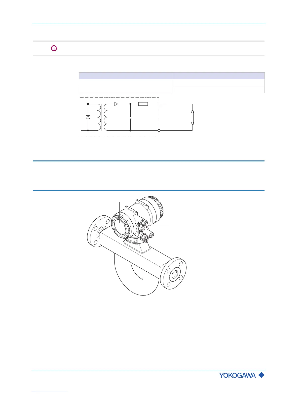
Status input Sin
Do not connect a signal source with electric voltage.
The status input is provided for use of voltage-free contacts with the following specifica-
tion:
Switching status Resistance
Closed < 200 Ω
Open > 100 kΩ
Fig.38: Status input connection
7.4.7 Connecting power supply and external devices
NOTICE
Risk of damage to the flow meter due to incorrect power supply
▶ The specified power supply must be observed (see General Specifications).
▶ The power-supply cable must be designed for the power supply used with a
minimum diameter of 0.5 mm.
1 Transmitter back cover
2 Power supply cable gland
 Loading...


