35
IM 04L51B01-18EN
ExampleofI/OMessageUsingRSLogix5000
ConnectionwithGX/GP
First, define the connection with recorder using RSLinx. Go to Communication on the menu
bar and select Configure Drivers.
Next, select Ethernet Devices and click Add New....
Enter a driver name. In this example, GX is entered but other names can also be
entered.
Enter the IP address of recorder and click OK.
GX is displayed on the RSWho list of RSLinx.
ConfigurationofCommunicationSettings
Open RSLogix 5000 and select a PLC used to communicate with recorder. Right-click
Ethernet in I/O Configuration and select New Module.
Click + to open the list. Select ETHERNET-MODULE and click OK. An ETHERNETMODULE
setup window will open.
The following shows an example of reading data in input/output channels 0001 to 0010 and
writing the data to communication channel data C001 to C020. Data can be accessed using
the INT32 type.
In the Name field, enter GX (or other communication connection name). Since data is
accessed using INT32, keep Comm Format as Data-DINT. In IP Address, enter the IP
address of recorder.
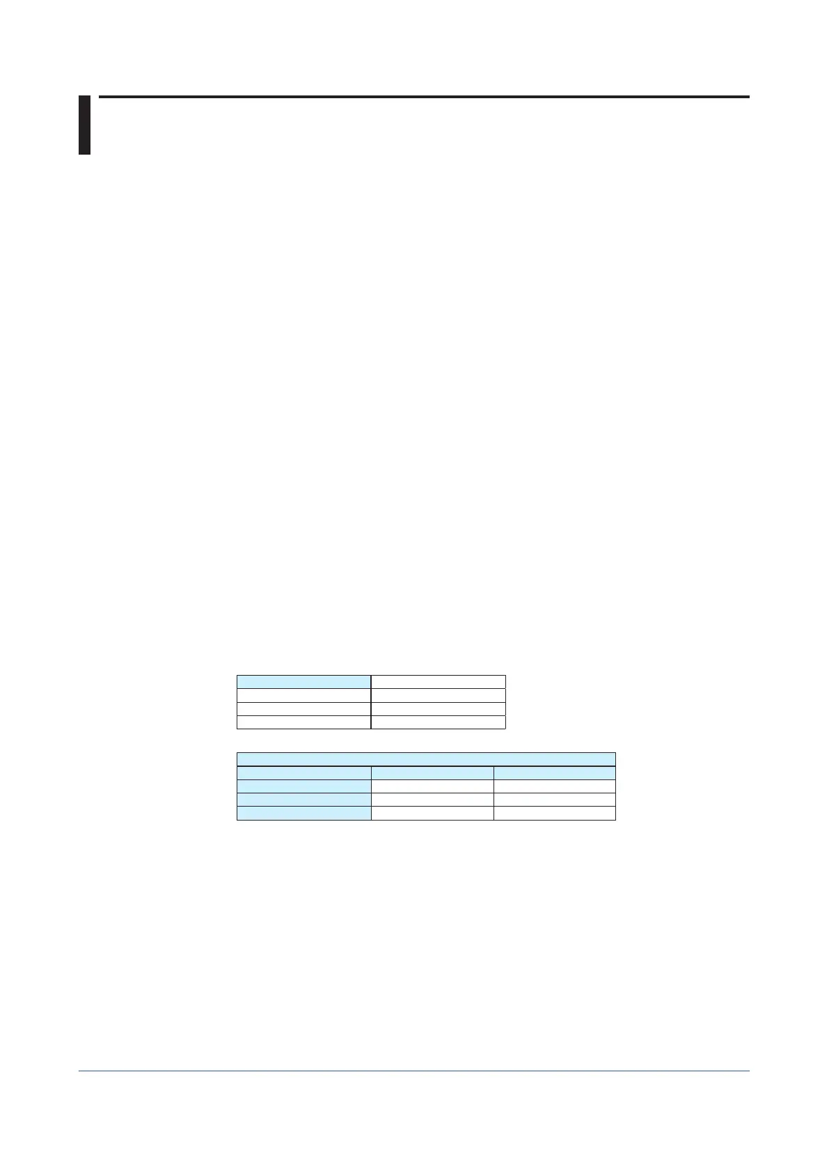
In Connection Parameter, define the input and output. In Input and Output, enter a
respective instance ID and size. In Configuration, enter an instance ID of 195 and a size
of 0.
NewModule
Name GX
Comm Format Data-DINT
Address/Host Name
IP Address 10.0.232.126
Connection Parameter
AssemblyInstance Size
Input 101 10 (32-bit)
Output 138 20 (32-bit)
Configuration 195 0 (8-bit)
Tag
In Controller Tag, the GX:I and GX:O tags to be used in control logic have been
made. Click + to expand the tag and see all the points of a size specified in the module
definition.