<Toc> <Ind>
3-3
TI 05C01E02-01E 1st Edition : Oct. 31, 2001-00
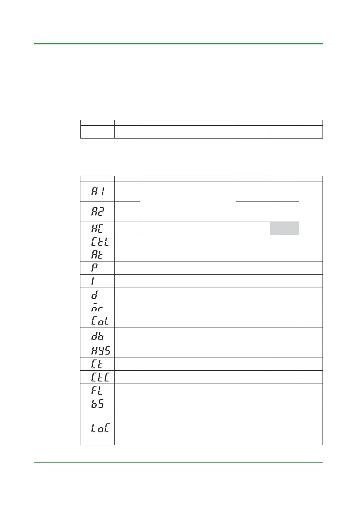
Code Name
(SP value display)
Target
setpoint
Setting range and unit
Minimum value (SPL) to maximum value (SPH) of target setpoint
range
Unit: °C/°F
Default User setting
SPL
CTL
Control mode
ONF(0): On/off control
PID(1): PID control
SLF(2): Dynamic auto tune control
(cannot be set for heating/cooling control)
SLF(2) : standard type;
PID(1) : heating/cooling
type
AT
Auto-tuning
OFF(0): Stop auto-tuning(AT)
ON(1): Start auto-tuning(AT)
OFF(0)
P
Proportional
band
1°C/°F to the temperature that corresponds to 100% of
the measured input range span
5% of measurd
input range span
I
Integral time
1 to 999 seconds;
OFF(0): no integral action
240 seconds
D
Derivative
time
1 to 999 seconds;
OFF(0): no derivative action
60 seconds
MR
Manual reset
-19.9 to 99.9 % : Standard type
-100 to 100 % : Heating/cooling type
50.0% :
Standard type;
0.0% :
Heating/cooling
type
COL
Cooling-side
gain
0.01 to 9.99 times
1.00 time
DB
Dead band
■ PID control Unit: °C/°F
Setting range: —(proportional band setting) to +(proportional band setting)
■ On/off control Unit: °C/°F
Setting range: —50 to +50% of measured input range span
0% of measured
input range span
HYS
Hysteresis for
on/off control
0°C/°F to the temperature that corresponds to 100% of
the measured input range span
0.5% of measured
input range span
CT
Control
output cycle
time
1 to 240 seconds
30 seconds
CTC
Cooling-side
control output
cycle time
1 to 240 seconds 30 seconds
FL
PV input filter
OFF(0), 1 to 120 seconds OFF(0)
BS
PV input bias
—100 to 100% of measured input range span
0% of measured
input range span
LOC
Key lock
0: No key lock
1: Prevents operations from being changed except for the
changing of SP in the operating display
2: Prevents all parameter changing operations
—1: Set -1 to enter the setup parameter setting display.
But if LOC=1 or 2 is already set, the parameter
value can not be changed by setting LOC=-1 only. To
change the parameter value, set LOC=0 at first (for
disabling keylock), then set LOC=-1 once again.
0
Code Name Setting range and unit Default User setting
Reference page
Reference page
HC
Heater disconnection
current measured
value
HC is not a parameter to be set. The current value (0 to 80) of heater
disconnection detector is displayed. Unit: A (ampere)
Settings:
When the display value is — — —, the heater current is not being measured.
A1
Alarm 1
setpoint
■ PV alarm Unit: °C/°F
Setting range: Minimum value to maximum value of
measured input range
■ Deviation alarm Unit: °C/°F
Setting range: —100 to 100% of measured input range
span
■ Heater disconnection alarm Unit: A (ampere)
Setting range: OFF(0), 1 to 80
(can be set for the alarm 1 setpoint only)
Max. value of
measured input
range (PV alarm)
A2
Alarm 2
setpoint
Min. value of
measured input
range (PV alarm)
Numbers in ( ) are the parmeter setpoints that apply
when the communication function is used.
Ex. OFF(0), ON(1)
P.4-9
P.4-12
P.4-16
P.4-17
P.4-5
P.6-1
P.6-6
P.6-7
P.6-2
P.6-4
P.6-5
P.6-4
P.5-8
P.5-8
P.6-1
P.4-8
P.6-8
P.6-8
P.5-2
P.5-1
P.5-7
(2) Operating Parameters: Parameters changed rather frequently during operation.
(1) Target Setpoint (SP)

 Loading...
