<Toc> <Ind>
6-1
TI 05C01E02-01E 1st Edition : Oct. 31, 2001-00
6. DESCRIPTION OF EACH FUNCTION
6.1 ON/OFF Control
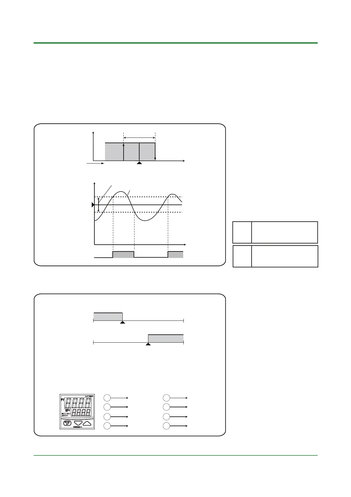
6.1.1 ON/OFF Control and Hysteresis
ON ON
OFF OFF
Hysteresis (HYS)
SP
Control output
PV
(Example of reverse action)
Control
output
Hysteresis
(HYS)
SPMeasured input value
OFF
IN ON/OFF control, since the only two
possible output states are ON and OFF,
the control output cycles are as shown in
the accompanying figure. ON/OFF
becomes quite narrow, so that if relay
output is used, chattering occurs. In this
case, the hysteresis should be set wider
to prevent relay chattering and for the
service life of the relay.
0 ¡C/¡F to the temperature
corresponding to 100% of the
measured input range (scale) span
HYS
Parameter Range
ONF: ON/OFF control
PID: PID control
SLF:
Dynamic Auto Tune control
CTL
ON
6.1.2 ON/OFF Control Application Example
•
An example on the left figure shows
two-step ON/OFF control using ON/OFF
control output and alarm output.
•
Alarm 1 is set to PV low limit alarm.
Alarm 1 output
Alarm 1 setpoint
ON
OFF
Control output
SP
ON OFF
•
Two-step ON/OFF Control
Terminal numbers for
UT130/UT150
Alarm 1 output
Control output
UT130/UT150
12
13
14
15
Terminal numbers for
UT152/UT155
Alarm 1 output
Control output
17
18
14
15

 Loading...
