<Toc> <Ind>
8-1
TI 05C01E02-01E 1st Edition : Oct. 31, 2001-00
8. INSTALLATION AND HARDWARE
SPECIFICATIONS
8.1 Installation
CAUTION
To prevent electric shock, the source of power to the controller must be turned off when mounting
the controller on to a panel.
NOTE
To install the controller, select a location where:
1. No-one may accidentally touch the terminals; 6. There are no resulting magnetic disturbances;
2. Mechanical vibrations are minimal; 7. The terminal board (reference junction compen-
3. Corrosive gas is minimal; sation element, etc.) is protected from wind;
4. The temperature can be maintained at about 8. There is no splashing of water; and
23°C with minimal fluctuation; 9. There are no flammable materials.
5. There is no direct heat radiation;
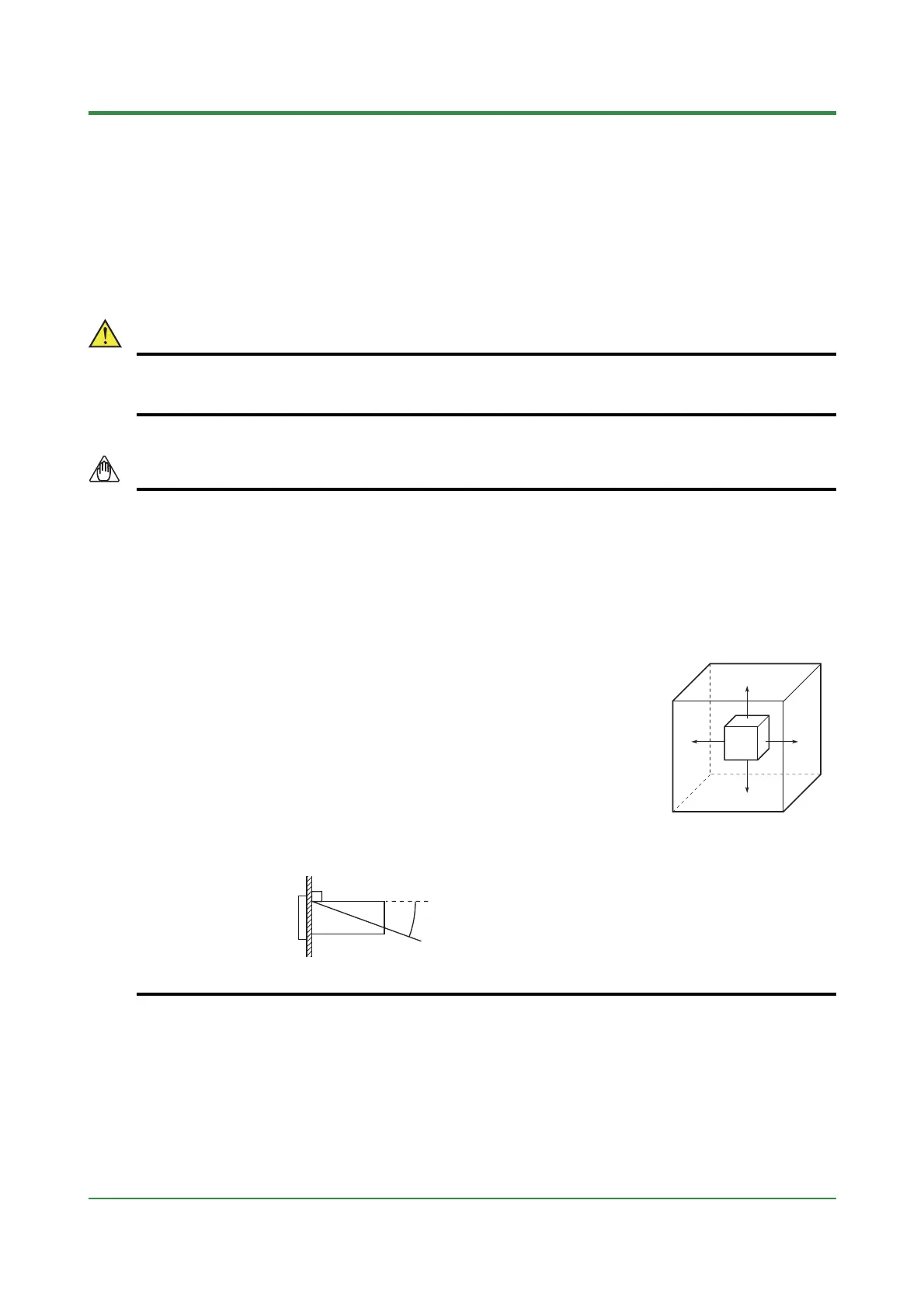
Never place the controller directly on flammable items.
If the controller has to be installed close to flammable items or equipment,
be sure to enclose the controller in shielding panels positioned at least
150mm away from each side. These panels should be made of either
1.43mm thick metal-plated steel plates or 1.6mm thick uncoated steel
plates.
● Mount the controller at an angle within 30° from horizontal with the screen facing upward. Do
not mount it facing downward.
150mm
150mm
150mm150mm
30°(MAX)

 Loading...
