<Toc> <Ind>
5-5
TI 05C01E02-01E 1st Edition : Oct. 31, 2001-00
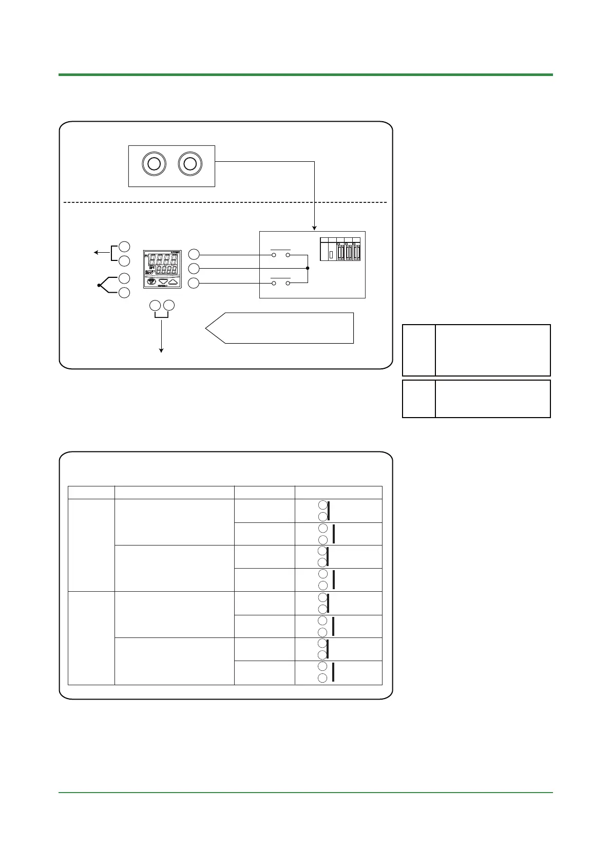
5.8 Switching RUN/ STOP
Operating panel
Start Stop
14
3
15
5
1
+
+
2
7
8
4
—
—
+
—
Control output
4 to 20mA
In STOP mode, control output value can be set
to 0% (4mA) or 100% (20mA) according to the
setting of the parameter "EOT".
SCR
To recorder
TC input
PV output
4 to 20mA
*The figure below shows the assignment
of contact input for UT150 when
the parameter "DIS"= 2.
COM
RUN/STOP
STOP when ON, RUN when OFF
PLC
SP1/SP2
<Central instrument room>
<Panel on site>
0:
Timer starts/stops, SP switching
1:Timer starts/stops,
RUN/STOPswitching
2
:
RUN/STOP switching, SP switching
DIS
Parameter Range
0: 0% (4mA DC)
1: 100% (20mA DC)
EOT
•
This function is available for
UT150/UT152/UT155 with the "/EX"
option.
•
RUN/STOP is switched using the
external contact inputs.
The external contact input terminals for
RUN/STOP switching are different
according to the parameter "DIS" setting.
Refer to the table below.
•
Set "1" or "2" for the setup parameter
"DIS" to switch RUN/STOP.
•
The symbol " STP " and PV value
appears alternately on PV display in
STOP mode.
PLC contact
•
The external contact input terminals for
RUN/STOP switching are different
according to the setup parameter "DIS"
setting.
•
External contact input terminals for RUN/STOP switching (for UT150/UT152/UT155 only)
Terminal number
Parameter "DIS" setpoint
Operating status
STOP
ON
Setup parameter
DIS = 1
Setup parameter
DIS = 2
UT150
RUN
STOP
RUN
4
5
4
5
OFF
ON
3
5
3
5
OFF
STOP
ON
Setup parameter
DIS = 1
Setup parameter
DIS = 2
UT152/
UT155
RUN
STOP
RUN
22
23
21
23
OFF
ON
22
23
21
23
OFF

 Loading...
