1-6
<Toc> <1. Installation>
IM 05D01D02-41E 4th Edition: May 31, 2006-00
● Cable Specifications and Recommended Cables
Purpose Name and Manufacturer
Power supply, grounding, relay contact outputs
600 V PVC insulated wires, JIS C 3307, 0.9 to 2.0 mm
2
Thermocouple Shielded compensating lead wires, JIS C 1610, X- - -
(See Yokogawa Electric's GS 6B1U1-E.)
RTD Shielded wires (three conductors), UL2482 (Hitachi Cable)
Other signals Shielded wires
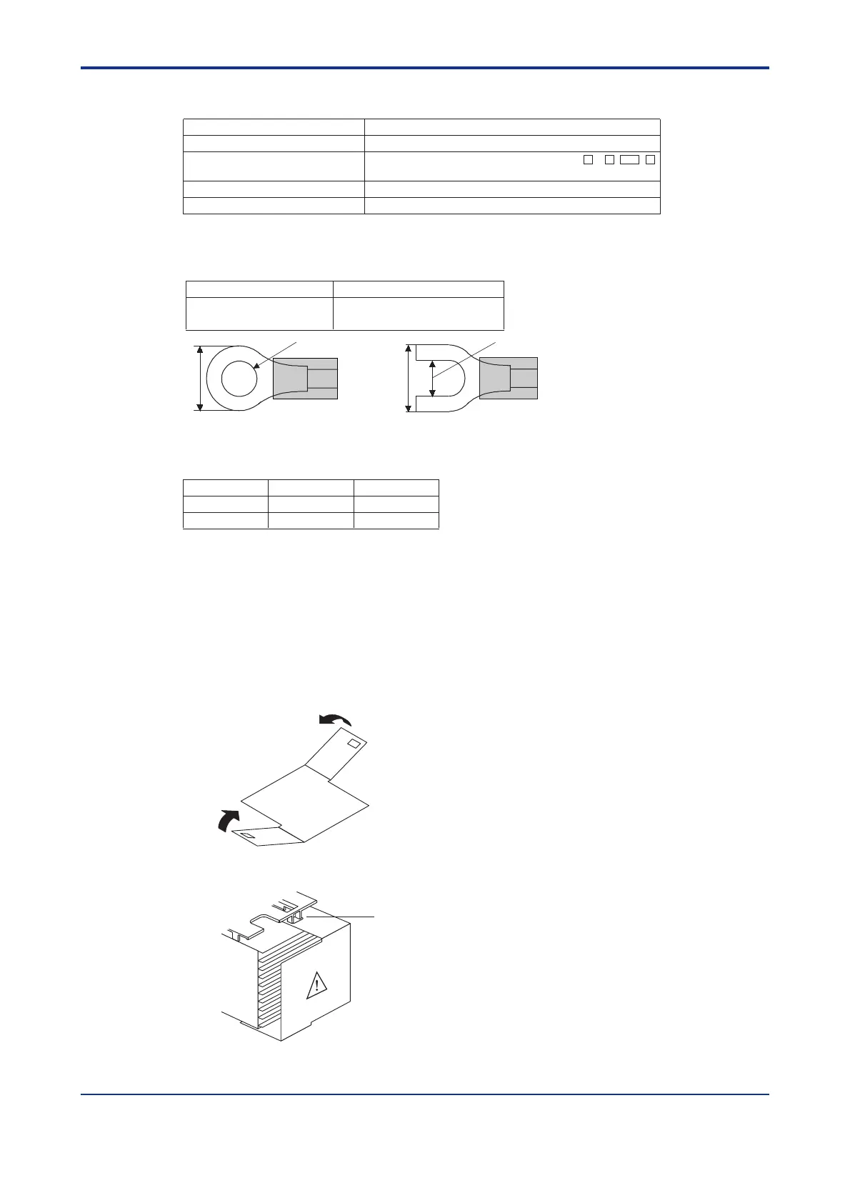
● Recommended Terminal Lugs
3.7mm
7 mm or less
3.7mm
7 mm or less
or
0.3 to 1.65 mm
2
0.8 N·m or less
Applicable wire size Tightening torque
● Terminal Covers (Optional parts)
Target Model Part Number Sales Unit
For UT350
T9115YD 1
For UT320
T9115YE 1
1. Before attaching the terminal cover, bend the side with the groove inward as shown in
Fig. A. Be careful not to bend it backwards. This not only marks it harder to attach the
cover but will also weaken its hold.
2. Fit the holes on the top and bottom of the terminal cover the projections on the brackets
(Fig. B) and lock in place. The figure right shows the attachment of a terminal cover to
UT controller.
Fold the cover in the direction
of the arrow.
Fit the cover hold
over the protrusion
on the mounting bracket.
Figure A
Figure B
Artisan Technology Group - Quality Instrumentation ... Guaranteed | (888) 88-SOURCE | www.artisantg.com

 Loading...


