<Toc> <5. Parameters>
5-11
IM 05D01D02-41E 4th Edition: May 31, 2006-00
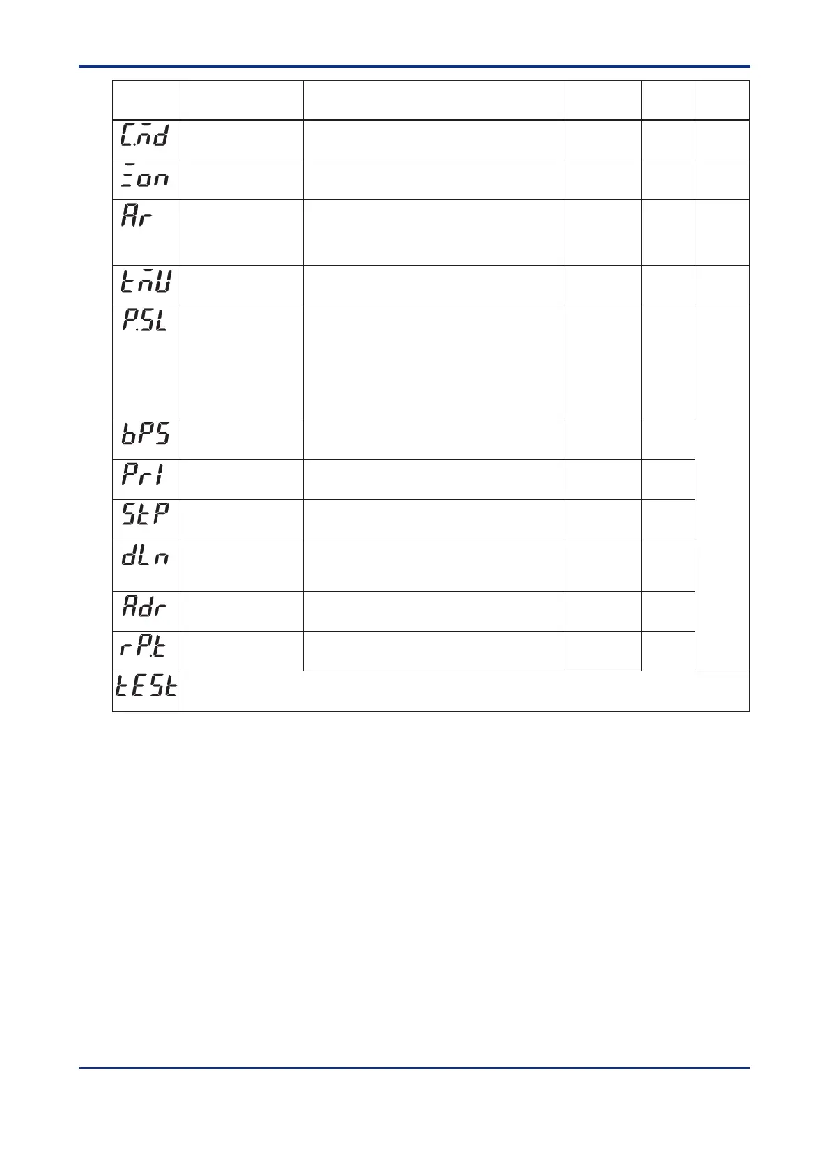
PID control mode
0: Standard PID control (with output bump at SP change)
1: Fixed Point control (without output bump at SP change)
Choose “Fixed Point Control” when controlling pressure or flow rate.
0
Zone PID selection OFF: SP selection
ON: Zone PID
OFF
(C.MD)
Ramp-rate time unit
setting
0: hour, 1: minute
Time unit of setpoint ramp-up (UPR) and setpoint
ramp-down (DNR)
0
(TMU)
Protocol selection 0
Baud rate 0: 600, 1: 1200, 2: 2400, 3: 4800, 4: 9600 (bps) 4
Parity 0: None
1: Even
2: Odd
1
Stop bit 1, 2 1
Data length
7, 8;
Fixed at 7, when the P.SL parameter is set to MODBUS (ASCII).
Fixed at 8, when the P.SL parameter is set to MODBUS (RTU)
or Ladder Communication.
8
0: PC link communication
1: PC link communication (with sum check)
2: Ladder communication
3: Coordinated master station 4: Coordinated slave station
7: MODBUS (ASCII) 8: MODBUS (RTU)
10: Coordinated slave station (loop-1 mode)
11: Coordinated slave station (loop-2 mode)
(10, 11: When the master station is in dual-loop control,
the slave station selects either of the loops to be controlled.)
(P.SL)
(BPS)
(PRI)
(STP)
(DLN)
Parameter
Symbol
Name of Parameter Setting Range and Description Initial Value
User Setting
Target Item
in CD-ROM
AUTO (0)Anti-reset windup
(Excess integration
prevention)
AUTO (0), 50.0 to 200.0%
Used when the control output travels up to 100% or down
to 0% and stays at this point.
The larger SP, the sooner PID computation
(integral computation) stops.
(AR)
(ZON)
Address 1 to 99
However, the maximum number of stations connectable
is 31.
1
Minimum response
time
0 to 10 (⫻ 10 ms) 0
(ADR)
(RP.T)
If this parameter symbol appears, press the SET/ENT key to return to the FUNC menu.
Caution: Do not change the setpoint of the TEST parameter, otherwise the controller will be disabled.
(TEST)
Ref.2.1(2)
Ref.4.1(2)
Ref.4.1(4)
Communication
function
Ref.2.1(4)
Artisan Technology Group - Quality Instrumentation ... Guaranteed | (888) 88-SOURCE | www.artisantg.com

 Loading...


