<Toc> <1. Installation>
1-9
IM 05D01D02-41E 4th Edition: May 31, 2006-00
Contact Inputs
• Purpose: Selection between target setpoints or Auto/Man modes, or for other pur-
poses
• Number of inputs: 2
• Input type: Non-voltage contact or transistor open collector input
• Input contact rating: 12 V DC, 10 mA or more
• On/off determination: For non-voltage contact input, contact resistance of 1 k or less
is determined as “on” and contact resistance of 20 k or more as “off.”
For transistor open collector input, input voltage of 2 V or less is determined as “on”
and leakage current must not exceed 100 A when “off.”
• Minimum status detection hold time: About 1 second.
Contact Outputs
• Purpose: Alarm output, FAIL output, and others
• Number of outputs: 3
• Relay contact rating: 240 V AC/1 A or 30 V DC/1 A (COM terminal is common.)
(FAIL output : 1b)
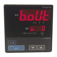
Display Specifications
• PV display:
UT350: 4-digit, 7-segment red LED display, character height of 20 mm
UT320: 4-digit, 7-segment red LED display, character height of 12 mm
• Setpoint display: 4-digit, 7-segment red LED display, character height of 9.3 mm (for
both UT350 and UT320)
• Status indicating lamps: LEDs
Artisan Technology Group - Quality Instrumentation ... Guaranteed | (888) 88-SOURCE | www.artisantg.com

 Loading...