IM 253401-01E
10-19
10
Using External In / Output
Note
• When the output items are to be sent by communication interface and they are set to V, A, P or dEG,
these items are then output. When the output item to be sent by communication is set to ALL, not only
the V and A data are output, but P and dEG data as well. When the output item to be sent by
communication is set to G-V to CG-P, the output data will not be the graph, but the numerical values.
• The orders are printed up to the maximum analysis order.
• When the fundamental frequency lies outside the measurement range of the harmonic analysis (display B
will show FrqEr), an attempt to output will result in an error code.
• When you set an element which is not the element of measurement (column B), an attempt to output will
result in an error code.
• When no analysis data are present, “––––” will be printed.
• There are cases where the active power value becomes negative. The corresponding bargraph will be
printed in thin print.
• When no plotter is connected, output time-out will result in an error code.
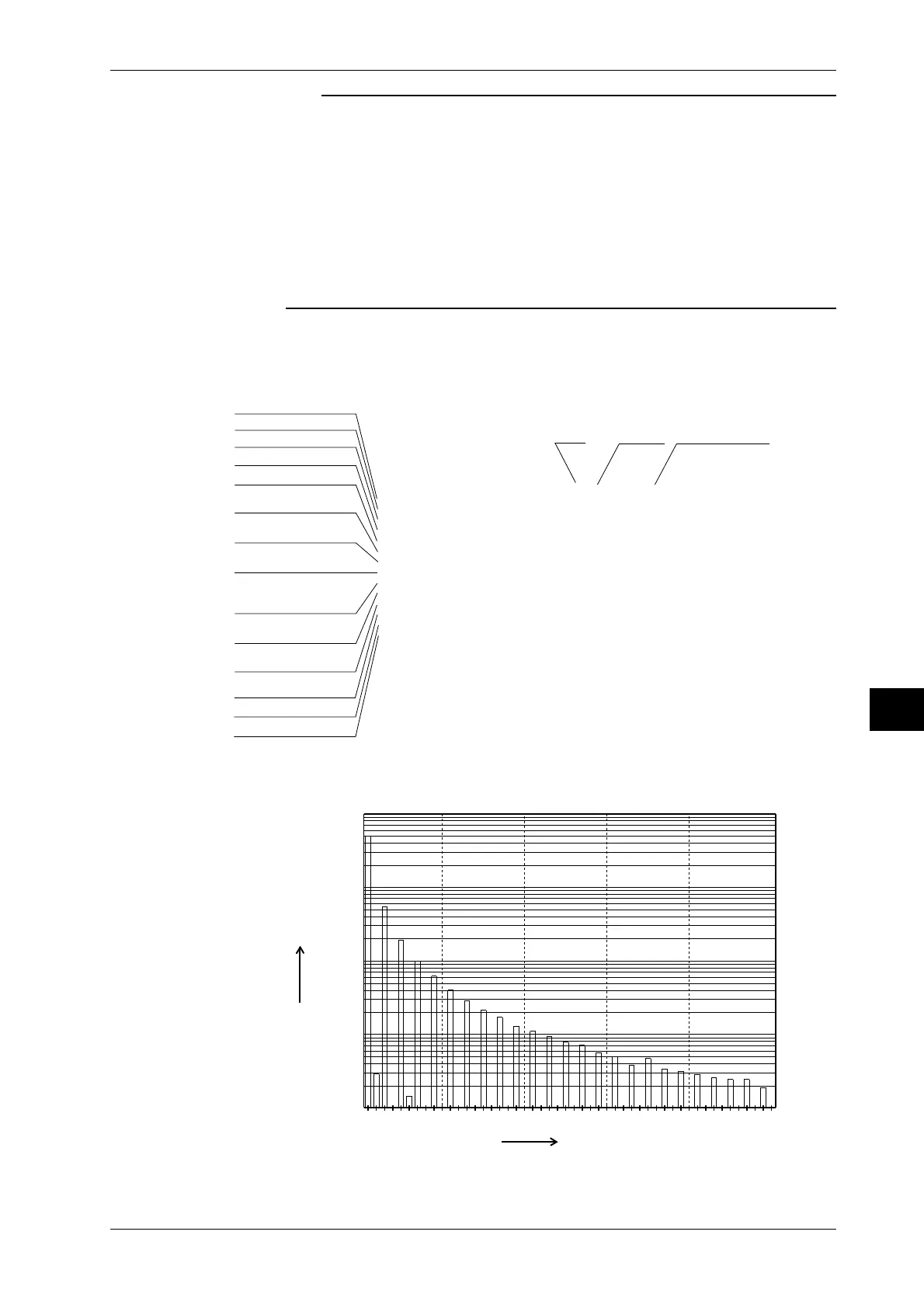
Example of Output to an External Plotter
• Output example in case of output item G-V of harmonic analysis data
(Slight differences may exist due to used plotter, etc.)
100.0
10.00
1.000
100.0m
10.00m
12010 30 40 50
Model : M/253503/HRM
V Range : 60V
A Range : 1A
Function : V 1
Sync : PLL V1
Freq V1 60.00 Hz
V1 rms 49.98 V
A1 rms 0.002 A
W1 = 0.02 W
DEG1 = LEAD 50.1 deg
PF1 = 0.641
V1 THD(IEC) = 12.01 %
A1 THD(IEC) = 95.58 %
=
=
=
####### Harmonic Voltage List #######
Or Volt [ V ] Cont [ % ] Or Volt [ V ] Cont [ % ]
1 49.62
35.5011.09
51.99 4.01
71.01 2.03
90.62 1.24
11 0.41 0.82
13 0.30 0.60
15 0.22 0.45
17 0.17 0.35
19 0.14 0.28
21 0.12 0.23
23 0.09 0.19
25 0.08 0.16
27 0.07 0.14
29 0.06 0.11
31 0.05 0.10
33 0.04 0.08
35 0.05 0.09
37 0.03 0.07
39 0.03 0.06
41 0.03 0.06
43 0.03 0.05
45 0.02 0.05
47 0.02 0.05
49 0.02 0.04
2
40.01 0.02
60.02 0.03
80.01 0.01
10 0.00 0.01
12 0.00 0.01
14 0.00 0.00
16 0.00 0.01
18 0.00 0.01
20 0.00 0.00
22 0.00 0.01
24 0.00 0.01
26 0.00 0.01
28 0.01 0.01
30 0.00 0.01
32 0.00 0.01
34 0.00 0.01
36 0.00 0.01
38 0.00 0.00
40 0.01 0.01
42 0.00 0.01
44 0.00 0.01
46 0.00 0.01
48 0.00 0.01
50 0.00 0.01
0.03 0.06
#### Harmonic Spectrum (Voltage) ####
[V]
Order
Analysis
Value
Relative Harmonic
Content
Voltage range
Current range
Function and element
PLL source
Frequency of PLL source
Rms value of 1st to 50th
order of voltage
Rms value of 1st to 50th
order of active power
Rms value of 1st to 50th
order of current
Phase angle between the
fundamental current and
fundamental voltage
Power factor of the
fundamental (1st order)
Harmonic distortion of
the voltage
Harmonic distortion of
the current
AVG(EXP 8)
Scaling
= OFF
= OFF
Averaging
Scaling
Analysis
Value
Order
10.9 Outputting to an External Plotter / Printer
 Loading...


