IM 253401-01E
6-2
6.2 Computing/Displaying the Phase Angle
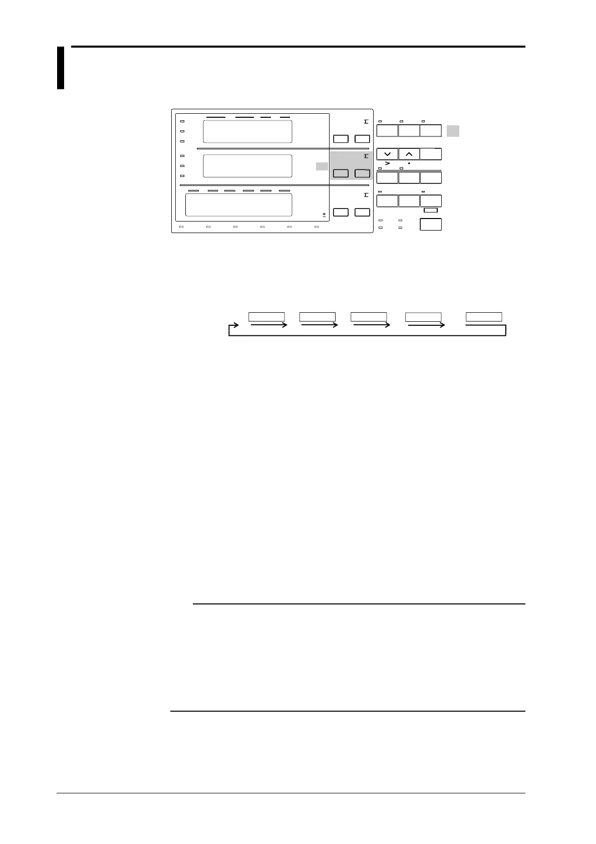
Relevant Keys
SCALING
AVG FILTER
STORE
RECALL
HARMONICS
SAMPLE
V OVER
A OVER
MODE
RMS
V MEAN
DC
A
B
C
hour
hour
min
min sec
VVA
m
Ak
var
MW
TIME
VPF
m
Ak
deg
MW
%
FUNCTION
AUTO AUTO
MODE
1Φ3W
VHz
m
Ak
h
MW
TRIG
V RANGE A RANGE HOLD
ENTER
INTEGRATOR
START
HARMONICS MEMORY INTEG SET
STOP RESET
REMOTE
INTERFACE OUTPUT
LOCAL
SETUP
h
SHIFT
WIRING
3Φ3W
3Φ4W
3V3A
ELEMENT
123
FUNCTION ELEMENT
123
FUNCTION ELEMENT
123
*Shows the operation panel of the WT130. For the differences
between WT110 and WT130, refer to section 2.2, page 2-2, 2-3
Displays
relevant
keys and
indicator
Operating Procedure
1 Selecting the Display Function
Select deg (phase angle) by pressing the FUNCTION key of display B.
Display
B
deg
FUNCTION FUNCTION FUNCTION
FUNCTION
FUNCTION
You can reverse the order by first pressing the SHIFT key followed by the FUNCTION key.
2 Selecting the Input Element
Select the input element by pressing the ELEMENT key of display B. The operation is the
same as the one described on page 5-1.
Explanation
Display Range and Units
Display range : G180.0 to d180.0 (G meaning phase lag, d meaning phase lead)
Unit : deg
Selecting the Display Function
When you select deg, the phase angle will be displayed.
Selecting the Input Element
The type of input element which can be selected depends on the model number. Make your
selection after having verified your model number.
• 1/2/3: Displays the measurement values of element 1/2/3
• ∑ : Refer to page 5-2.
Note
• Changing the measurement mode might result in different computed results, even when the input signal
is the same. For more details on the measurement mode, refer to page 4-1.
• When either the voltage or current drops below 0.5% of the measurement range, dEGErr will be
displayed.
• Distinction between phase lag and lead can be made properly, only when both voltage and current are
sine waves, and when the percentage of voltage or current input relating to the measurement range does
not fluctuate much.
• If the computed result of the power factor exceeds 1, the display will be as follows.
- when the power factor ranges between 1.001 to 2.000; the phase angle displays 0.0;
- when the power factor is 2.001 or more, the phase angle displays dEGErr.
 Loading...


