IM 253401-01E
8-6
8.4 Setting the Harmonic Order and Displaying the
Results of Harmonic Analysis
Relevant Keys
SCALING
AVG FILTER
STORE
RECALL
HARMONICS
SAMPLE
V OVER
A OVER
MODE
RMS
V MEAN
DC
A
B
C
hour
hour
min
min sec
VVA
m
Ak
var
MW
TIME
VPF
m
Ak
deg
MW
%
FUNCTION
AUTO AUTO
MODE
1Φ3W
VHz
m
Ak
h
MW
TRIG
V RANGE A RANGE HOLD
ENTER
INTEGRATOR
START
HARMONICS MEMORY INTEG SET
STOP RESET
REMOTE
INTERFACE OUTPUT
LOCAL
SETUP
h
SHIFT
WIRING
3Φ3W
3Φ4W
3V3A
ELEMENT
123
FUNCTION ELEMENT
123
FUNCTION ELEMENT
123
*Shows the operation panel of the WT130. For the differences
between WT110 and WT130, refer to section 2.2, page 2-2, 2-3
Displays
relevant
keys and
indicator
Operating Procedure
The following operations assume that the harmonic analysis function is turned ON.
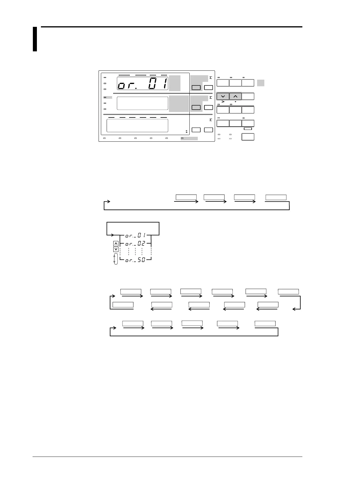
Setting the Harmonics Order
1. Light up the display function indicator of display A.
Display
A
Light up display function
FUNCTION FUNCTION FUNCTION
FUNCTION
2. Set the harmonics order.
(Display A)
Displaying the Values of Harmonic Analysis
Displays each analysis value after having set the display function of either display B or C.
FUNCTION
VA W PF
FUNCTION
FUNCTION
FUNCTION
FUNCTION
FUNCTION
V% A%
W%Vdeg A% V%
Adeg
FUNCTION FUNCTIONFUNCTIONFUNCTIONFUNCTION
Display
B
FUNCTION
VAWV Hz
FUNCTION
FUNCTION
FUNCTION FUNCTION
A Hz
Display
C
Explanation
Setting the Order of Harmonics
The maximum order for which analysis results can be displayed varies depending on the
frequency of the fundamental.
Example
• When the fundamental frequency is 50Hz, up to 50 orders can be displayed;
• When the fundamental frequency is 400Hz, up to 30 orders can be displayed.
When an order is set exceeding the maximum order, display B will change to the dot display.
Refer to Ch. 15 for more details on upper limits of analysis orders.
 Loading...


