IM 253401-01E
3-11
3
Before Operation
3.6 Wiring the Measurement Circuit when Using the External Sensor
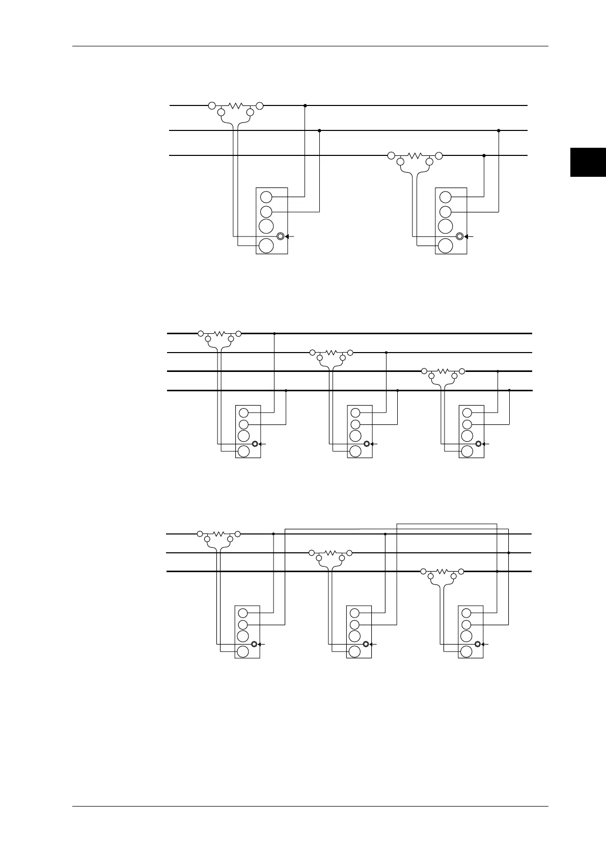
Wiring diagram for three-phase, three-wire system with external shunt
connected (253502, 253503)
SOURCE LOAD
±A
OUT LOUT H
±A
OUT L
OUT H
R
S
T
Ext. sensor input
terminal (EXT)
A
V
±
±
Input terminal
(ELEMENT1)
Ext. sensor input
terminal (EXT)
A
V
±
±
Input terminal
(ELEMENT3)
Wiring diagram for three-phase, four-wire system with external shunt
connected (253503)
SOURCE LOAD
±A
OUT LOUT H
±A
OUT LOUT H
R
S
T
N
±A
OUT LOUT H
Ext. sensor
input terminal
(EXT)
A
V
±
±
Input terminal
(ELEMENT3)
Ext. sensor input
terminal (EXT)
A
V
±
±
Input terminal
(ELEMENT1)
Ext. sensor input
terminal (EXT)
A
V
±
±
Input terminal
(ELEMENT2)
Wiring diagram for three-voltage, three-current system with external shunt
connected (253503)
SOURCE LOAD
±A
OUT LOUT H
±A
OUT LOUT H
R
S
T
±A
OUT LOUT H
Ext. sensor
input terminal
(EXT)
A
V
±
±
Input terminal
(ELEMENT3)
Ext. sensor input
terminal (EXT)
A
V
±
±
Input terminal
(ELEMENT1)
Ext. sensor input
terminal (EXT)
A
V
±
±
Input terminal
(ELEMENT2)
 Loading...


