EasyManua.ls Logo

York CHAMPION B1HH018 User Manual

York CHAMPION B1HH018
28 pages
To Next Page IconTo Next Page
Page #1 background imageLoading...
Page #1 background image
GENERAL
YORK Model B1HH units are factory assembled heat pumps
designed for outdoor installation on a roof top or a slab. Field-in-
stalled electric heater accessories are available to provide supple-
mental electric heat combined with electric cooling and heating.
The units are completely assembled on rigid, removable base
rails. All piping, refrigerant charge, and electrical wiring is
factory installed and tested. The units require only electric
power and duct connections at the point of installation.
The electric heaters have nickel-chrome resistance wire ele-
ments and utilize single point power connection.
INSPECTION
As soon as a unit is received, it should be inspected for possible
damage during transit. If damage is evident, the extent of the
damage should be noted on the carrier’s freight bill. A separate
request for inspection by the carrier’s agent should be made in
writing. Refer to Form 50.15-NM for additional information.
REFERENCE
Additional information on the design, installation, operation and
service of this equipment is available in the following reference
forms:
55.70-N1 — General Installation
55.70-N2 Pre-start & Post-start Check List
511.26-N1.1V — Electric Heater Accessory
REPLACEMENT PARTS
Refer to Replacement Parts Manual for complete listing of
replacement parts on this equipment.
All forms referenced in this instruction may be ordered from:
YORK Publications Distribution Center
Standard Register
2101 West Tecumseh Road
Norman, Oklahoma 73069
FAX (877) 379-7920
Installer should pay particular attention to the words:
NOTE, CAUTION
and
WARNING
. Notes are intended to clarify or make
the installation easier. Cautions are given to prevent equipment damage. Warnings are given to alert installer that personal injury
and/or equipment damage may result if installation procedure is not handled properly.
CAUTION
THIS PRODUCT MUST BE INSTALLED IN STRICT COMPLIANCE WITH THE ENCLOSED INSTALLATION INSTRUCTIONS
AND ANY APPLICABLE LOCAL, STATE, AND NATIONAL CODES INCLUDING, BUT NOT LIMITED TO, BUILDING, ELEC-
TRICAL, AND MECHANICAL CODES
WARNING
INCORRECT INSTALLATION MAY CREATE A CONDITION WHERE THE OPERATION OF THE PRODUCT COULD CAUSE
PERSONAL INJURY, PROPERTY DAMAGE AND/OR DEATH.
WARNING
DE-ENERGIZE THE ELECTRICAL POWER TO THE UNIT BEFORE ATTEMPTING TO INSPECT, REPAIR OR PERFORM
MAINTENANCE TO THE UNIT.
CHAMPION
®
SERIES
SINGLE PACKAGE HEAT PUMPS
Supersedes: 511.18-N2Y (498)
511.18-N2Y (799)
035-16707-000
INSTALLATION INSTRUCTION
®
MODELS B1HH018 THRU 060
1.5 THRU 5 TON
(12 SEER)
Question and Answer IconNeed help?

Do you have a question about the York CHAMPION B1HH018 and is the answer not in the manual?

York CHAMPION B1HH018 Specifications

General IconGeneral
BrandYork
ModelCHAMPION B1HH018
CategoryHeat Pump
LanguageEnglish

Summary

GENERAL UNIT INFORMATION

Unit Inspection Procedures

Inspect unit for transit damage and report any issues to the carrier.

Reference Materials

Lists available documentation for installation, operation, and service of the equipment.

Replacement Parts Guidance

Directs users to the Replacement Parts Manual for part listings and ordering.

INSTALLATION LIMITATIONS

INSTALLATION GUIDELINES

Location Selection Criteria

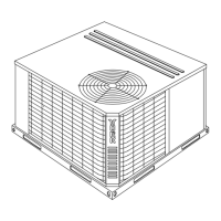
Guidelines for selecting a suitable outdoor installation location, considering air supply and ground/roof pads.

Rigging and Handling Procedures

Instructions for safely moving and lifting the unit using slings, spreader bars, or forklifts.

INSTALLATION COMPONENTS AND WIRING

Clearances and Ductwork

Specifies minimum clearances and requirements for ductwork installation.

Filters and Condensate Drain

Details filter requirements and condensate drain setup procedures.

Service Access and Thermostat

Identifies service panels and guidelines for thermostat installation.

Power and Control Wiring

Details field wiring requirements, grounding, disconnects, and wire sizing per codes.

Compressor Information

Notes that compressor mountings are factory-adjusted and ready for operation.

WIRING DIAGRAMS

Control Wiring Diagram

Illustrates the typical connections for thermostat and unit control signals.

Power Wiring Diagram

Shows typical field wiring connections for single and three-phase power supply.

MINIMUM CLEARANCES

Front Clearance

Minimum 12" clearance required in front of the unit.

Back Clearance

Minimum 0" clearance required at the back of the unit.

Left Side Clearance

Minimum 24" clearance for filter access on the left side.

Right Side Clearance

Minimum 24" clearance on the right side of the unit.

Below Unit Clearance

Minimum 0" clearance required below the unit.

Above Unit Clearance

Minimum 36" clearance for condenser air discharge above the unit.

SEQUENCE OF OPERATION

Anti-short Cycle Timer

Prevents compressor restart within five minutes of the last cycle or power interruption.

Cooling Operation Details

Describes thermostat signals and unit response for cooling mode with PSC motor.

Heating Operation Details

Describes thermostat signals and unit response for heating mode with PSC motor.

Defrost Cycle Operation

Initiates and terminates defrost cycle based on sensor and time, energizes electric heat if equipped.

Safety Switch Operation

Protects system against pressure/temperature issues, with lockout features.

Electric Heat Limit Switch

Responds to duct over-temperature conditions, initiating soft/hard lockout.

OWNER APPROVAL AND THERMOSTAT SIGNALS

Secure Owner's Approval

Ensure the owner understands system operation, controls, and basic functions.

NORMAL MAINTENANCE PROCEDURES

Filter Maintenance

Periodic inspection and cleaning/replacement of filters is necessary for efficiency.

Motor Maintenance

Indoor and outdoor fan motors are permanently lubricated and require no maintenance.

Outdoor Coil Cleaning

Keep the outdoor coil clean by removing dirt to maintain performance and prevent damage.

TROUBLESHOOTING

ELEMENTARY WIRING DIAGRAM

BHH060 Wiring Diagram

Typical elementary wiring diagram for BHH060 models with 208/230-1-60 power supply.

WIRING DIAGRAM LEGEND

WIRING DIAGRAM NOTES

Related product manuals