EasyManua.ls Logo

York CHAMPION B1HH048 User Manual

York CHAMPION B1HH048
28 pages
To Next Page IconTo Next Page
Page #1 background imageLoading...
Page #1 background image
GENERAL
YORK Model B1HH units are factory assembled heat pumps
designed for outdoor installation on a roof top or a slab. Field-
installed electric heater accessories are available to provide
supplemental electric heat combined with electric cooling and
heating.
The units are completely assembled on rigid, removable
base rails. All piping, refrigerant charge, and electrical wiring
is factory installed and tested. The units require only electric
power and duct connections at the point of installation.
The electric heaters have nickel-chrome resistance wire ele
-
ments and utilize single point power connection.
INSPECTION
As soon as a unit is received, it should be inspected for possi
-
ble damage during transit. If damage is evident, the extent of
the damage should be noted on the carrier's freight bill. A
separate request for inspection by the carrier's agent should
be made in writing. Refer to Form 50.15-NM for additional in
-
formation.
REFERENCE
Additional information on the design, installation, operation
and service ofthis equipment is available in the following refer-
ence forms:
55.70-N1 — General Installation
55.70-N2 — Pre-start & Post-start Check List
511.26-N1.1V — Electric Heater Accessory
REPLACEMENT PARTS
Refer to Replacement Parts Manual for complete listing of
replacement parts on this equipment.
Installershouldpayparticular attention to the words: NOTE, CAUTION and WARNING.Notes
areintendedtoclarify or make the
installation easier. Cautions
are given to prevent equipment damage. Warnings are given to alert installer that personal injury
and/or equipment damage may result if installation procedure is not handled properly.
CAUTION
THIS PRODUCT MUST BE INSTALLED IN STRICT COMPLIANCE WITH THE ENCLOSED INSTALLATION INSTRUCTIONS
AND ANY APPLICABLE LOCAL, STATE, AND NATIONAL CODES INCLUDING, BUT NOT LIMITED TO, BUILDING, ELEC
-
TRICAL, AND MECHANICAL CODES
WARNING
INCORRECT INSTALLATION MAY CREATE ACONDITION WHERE THE OPERATION OF THE PRODUCT COULD CAUSE
PERSONAL INJURY, PROPERTY DAMAGE AND/OR DEATH.
WARNING
DE-ENERGIZE THE ELECTRICAL POWER TO THE UNIT BEFORE ATTEMPTING TO INSPECT, REPAIR OR PERFORM
MAINTENANCE TO THE UNIT.
CHAMPION® SERIES
SINGLE PACKAGE HEAT PUMPS
Supersedes: 66297-YIM-B-1004
66297-YIM-C-0205
INSTALLATION INSTRUCTION
®
MODELS B1HH018 THRU 060
1.5 THRU 5 TON
(12 SEER)
Question and Answer IconNeed help?

Do you have a question about the York CHAMPION B1HH048 and is the answer not in the manual?

York CHAMPION B1HH048 Specifications

General IconGeneral
ModelCHAMPION B1HH048
CategoryHeat Pump
Tonnage4 Ton
Cooling Capacity (BTU/h)48000
Heating Capacity (BTU/h)48000
SEER Rating16
HSPF Rating9.0
Refrigerant TypeR-410A
Voltage (V)208/230
Phase1
Sound Rating (Outdoor Unit, dB)74

Summary

Installation Instruction Overview

General Unit Description

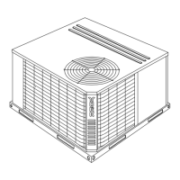
Factory assembled heat pumps designed for outdoor installation on a roof top or a slab.

Unit Inspection Procedure

Inspect the unit for possible damage during transit and note any findings.

Important Safety Notices

Installer must pay attention to NOTE, CAUTION, and WARNING messages.

Installation Guidelines and Limitations

Installation Limitations and Codes

Units must be installed in accordance with national and local safety codes.

Unit Placement and Rigging

Guidelines for selecting a location and safely rigging or handling the unit.

Installation Details and Components

Clearances, Ductwork, and Filters

Required clearances, ductwork adaptation, and filter installation/maintenance.

Condensate Drain and Service Access

Requirements for condensate drain installation and access panels for service.

Thermostat and Wiring Requirements

Thermostat location guidelines and power/control wiring compliance.

Wiring Diagrams

Control Wiring Details

Diagram for thermostat and unit terminal strip connections.

Power Wiring Connections

Typical field wiring diagram for single and three phase power supply.

Unit Specifications

Physical Data

Table listing physical characteristics of the unit models.

Basic Unit Electrical Data

Provides electrical specifications for the unit's basic operation.

Electric Heat Electrical Data

Heat Pump/Electric Heat Accessory Electrical Data

Electrical data for units equipped with electric heat accessory.

Performance Data Tables

Cooling Superheat Data

Superheat values for cooling operation at various CFM and temperatures.

Heating Superheat Data

Superheat values for heating operation at various CFM and temperatures.

Blower Performance Specifications

Supply Air Blower Performance

Performance data for side and bottom supply air blowers.

Static Pressure and Clearances

Additional Static Pressure Resistance

Resistance values for components at different CFM.

Installation Clearances

Minimum clearances required for installation and operation.

Unit Dimensions

Physical Dimensions

Provides overall dimensions and specific measurement points for the unit.

Sequence of Operation and Safety Features

Unit Operating Modes

Describes unit operation for cooling, heating, and defrost modes.

Safety Switch and Limit Operation

Explains operation of heat pump safety switches and electric heat limit switches.

Thermostat Signal Logic

Single Phase Thermostat Signals

Defines thermostat signal states and corresponding board functions for single phase units.

Maintenance and Three-Phase Signals

Three Phase Thermostat Signals

Defines thermostat signal states and board functions for three phase units.

Normal Maintenance Procedures

Outlines routine maintenance procedures for the unit.

Troubleshooting and Wiring Diagrams

Troubleshooting Guide

Provides guidance for diagnosing and resolving common unit issues.

Wiring Diagram: 208/230-1-60 Power Supply

Illustrates electrical connections for 208/230-1-60 power supply.

Wiring Diagram Reference

Wiring Diagram Legend

Explains symbols and abbreviations used in wiring diagrams.

Wiring Diagram Notes

Provides important notes and cautions regarding wiring and installation.

Three-Phase Wiring Diagrams

Wiring Diagram: 208/230-3-60 Power Supply

Illustrates electrical connections for 208/230-3-60 power supply.

Three-Phase Wiring Diagram Details

Wiring Diagram Legend (208/230-3-60)

Explains symbols used in 208/230-3-60 wiring diagrams.

Wiring Diagram Notes (208/230-3-60)

Provides important notes for 208/230-3-60 wiring diagrams.

Low Voltage Three-Phase Wiring

Wiring Diagram: 460-3-60 Power Supply

Illustrates electrical connections for 460-3-60 power supply.

Low Voltage Three-Phase Wiring Details

Wiring Diagram Legend (460-3-60)

Explains symbols used in 460-3-60 wiring diagrams.

Wiring Diagram Notes (460-3-60)

Provides important notes for 460-3-60 wiring diagrams.

Related product manuals