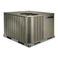
GENERAL
YORK Model B1HH units are factory assembled heat pumps
designed for outdoor installation on a roof top or a slab. Field-
installed electric heater accessories are available to provide
supplemental electric heat combined with electric cooling and
heating.
The units are completely assembled on rigid, removable
base rails. All piping, refrigerant charge, and electrical wiring
is factory installed and tested. The units require only electric
power and duct connections at the point of installation.
The electric heaters have nickel-chrome resistance wire ele
-
ments and utilize single point power connection.
INSPECTION
As soon as a unit is received, it should be inspected for possi
-
ble damage during transit. If damage is evident, the extent of
the damage should be noted on the carrier's freight bill. A
separate request for inspection by the carrier's agent should
be made in writing. Refer to Form 50.15-NM for additional in
-
formation.
REFERENCE
Additional information on the design, installation, operation
and service ofthis equipment is available in the following refer-
ence forms:
• 55.70-N1 — General Installation
• 55.70-N2 — Pre-start & Post-start Check List
• 511.26-N1.1V — Electric Heater Accessory
REPLACEMENT PARTS
•
Refer to Replacement Parts Manual for complete listing of
replacement parts on this equipment.
Installershouldpayparticular attention to the words: NOTE, CAUTION and WARNING.Notes
areintendedtoclarify or make the
installation easier. Cautions
are given to prevent equipment damage. Warnings are given to alert installer that personal injury
and/or equipment damage may result if installation procedure is not handled properly.
CAUTION
THIS PRODUCT MUST BE INSTALLED IN STRICT COMPLIANCE WITH THE ENCLOSED INSTALLATION INSTRUCTIONS
AND ANY APPLICABLE LOCAL, STATE, AND NATIONAL CODES INCLUDING, BUT NOT LIMITED TO, BUILDING, ELEC
-
TRICAL, AND MECHANICAL CODES
WARNING
INCORRECT INSTALLATION MAY CREATE ACONDITION WHERE THE OPERATION OF THE PRODUCT COULD CAUSE
PERSONAL INJURY, PROPERTY DAMAGE AND/OR DEATH.
WARNING
DE-ENERGIZE THE ELECTRICAL POWER TO THE UNIT BEFORE ATTEMPTING TO INSPECT, REPAIR OR PERFORM
MAINTENANCE TO THE UNIT.
CHAMPION® SERIES
SINGLE PACKAGE HEAT PUMPS
Supersedes: 66297-YIM-B-1004
66297-YIM-C-0205
INSTALLATION INSTRUCTION
®
MODELS B1HH018 THRU 060
1.5 THRU 5 TON
(12 SEER)