FORM 160.73-PW1(405)
11
YORK INTERNATIONAL
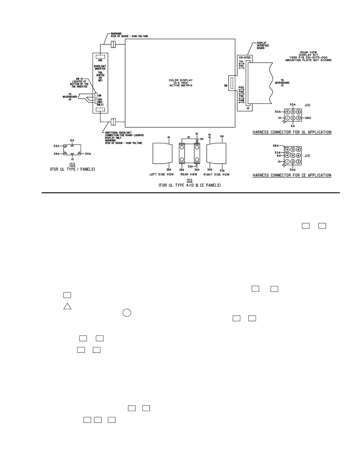
FIG. 5 – DISPLAY INTERFACE BOARD
NOTES:
1. This wiring diagram describes the standard elec tron ic
con trol scheme for use with an electromechanical start er.
For details of standard modifi cations, refer to Product
Form 160.54-PW7.
2. Field wiring to be in accordance with the National
Elec tri cal Code as well as all other applicable codes and
spec i fi ca tions. See Product Form 160.54-PW7 for fi eld
wiring con nec tions.
3. Numbers along the left side of diagram are line iden ti -
fi ca tion numbers. The numbers along the right side in di cate
the line num ber location of relay contacts. An un der lined
con tact lo ca tion signifi es a normally closed con tact.
4. Main control panel Class 1 fi eld wiring terminal con-
nec tion points are indicated by numbers within a rect an gle,
i.e. 15 . Main con trol panel factory wiring terminal con-
nec tion points are in di cat ed by numbers within a tri an gle,
i.e. 5 . Com po nent terminal markings are in di cat ed by
num bers within a circle, i.e. C1 . Num bers ad ja cent to
cir cuit lines are the cir cuit iden ti fi ca tion num bers.
5. To cycle unit on and off automatically with contacts
oth er than those shown, install a cycling device between
ter mi nals 1 & 13 (line 37) (see note 9). If a cycling
device is installed, jumper must be removed between
ter mi nals 1 & 13 .
6. Compressor motor starter with starter interlock con tacts
(rat ed 0.5 to 1.0 amp @ 24 volts A.C.) must be per Form
160.45-PA5.1. Control panel shall be grounded.
7. Units installed in Canada must have a fi eld supplied CSA
approved 30 amp disconnect switch and a 20 amp dual
element fuse mounted external to control panel for 115
volt control supply.
8. To stop unit and not permit it to start again, install a
stop device between terminals 1 & 8 (Line 33) (see
note 9). A re mote start-stop switch may be connected
to ter mi nals 1 , 7 & 8 (Lines 32 & 33) (see note 9).
Remote start-stop switch (Line 32) is op er a tive only in
the “re mote” op er at ing mode.
9. Device contact rating to be 5 milliamperes @ 115 volts
A.C.
11. Contact rating is 5 Amps resistive @ 120 volts A.C. or
240 volts A.C.
13. To check motor rotation on initial start-up, install
mo men tary switch between terminals 24 & 25 (line
41). De press start switch. After approx. 30 seconds, jog
mo tor with mo men tary switch. When proper rotation is
ob tained, replace mo men tary switch with jumper. Switch
must have a min i mum con tact rat ing of 2 FLA., 10 LRA
at 115 Volts A.C.
14. Motor overload (CM) is set to trip at 105% FLA. During
mo men tary power interruption (power fault), contact
opens for 1 sec ond.
15. For high and low voltage units, the factory supplied
jump er be tween 15 & 53 must be removed when
elec tro me chan i cal start er overloads and/or safety de vic es
are used. For high voltage (2300-4160) UL and CUL ap-
proved units only, elec tro me chan i cal com pres sor motor
starter over loads (nor mal ly closed) must be con nect ed
be tween 15 & 53 .
16. Contact rating is 5 Amps resistive @ 250 Volts A.C. &
30 Volts D.C., 2 Amp inductive (.4 PF) @ 250 Volts A.C.
& 30 Volts D.C.
17. Each 115VAC fi eld-connected inductive load: i.e. relay
coil, mo tor starter coil, etc., shall have a transient sup-
pres sor wired in parallel with its coil, physically located
at the coil. Spare tran sient suppressors and control cir cuit
fuses are sup plied in a bag attached to green ground
screw in lower left corner of control panel.
18. For units with fl ash miniature card software version
C.MLM.01.00 through C.MLM.01.03 the condenser
water pump should be wired to terminal 164 of TB2
instead of terminal 151, and the wire from terminal 22 of
TB5 to terminal 150 TB2 shall not be installed. For soft-
ware version C.MLM.01.04 and higher, the condenser
pump connection should be as shown in the fi gure.
19. Resistor for use with Belimo actuator. Remove resis-
tor if hot gas actuator is a Dodge Engineering, Bray or
Landis-Staefa actuator.
LD08956
DISPLAY INTERFACE BOARD

 Loading...