OPTIONAL PARTS
TC-17006-rev.1
3-5
3 Install the IR receiver kit using the length of
connecting cable (accessory).
The cable length is approximately 17 ft. (5m).
4
Open the cover of the IR receiver kit.
Push the slotted screwdriver with a tip width of
approximately 1/4 inch (6mm) into the slot of the
IR receiver kit cover and rotate it to open the
cover as shown in the gure at the right.
1
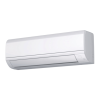
Perform the installation work for the IR receiver kit while the indoor unit is being installed.
2
Turn OFF the power supply for the indoor unit if the IR receiver kit is attached after the indoor unit is
installed.
5
Mount the IR receiver kit onto the wall or the ceiling surface as shown below.
Situation A
(1) Secure the bracket.
Situation B
(1) Prepare the eld-supplied switch box (JIS
Box). (JIS C8340)
Slot
t
Mounting Bracket
Rotate
Push and rotate.
Slotted Screwdriver
(Tip Width:
A
Securing Screw
(Accessory)
Secure the bracket with four
accessory securing screws.
Any of the following Switch Boxes
can be utilized.
1. Switch Box for One Switch
(Without Cover)
2. Small Switch Box for One Switch
(Without Cover)
3. Switch Box for One Switch
(With Cover)
Metal Conduit
(larger than I.D. φ13/16 inch (φ20mm)
Two Securing Screws (M4, Field-Supplied)
 Loading...