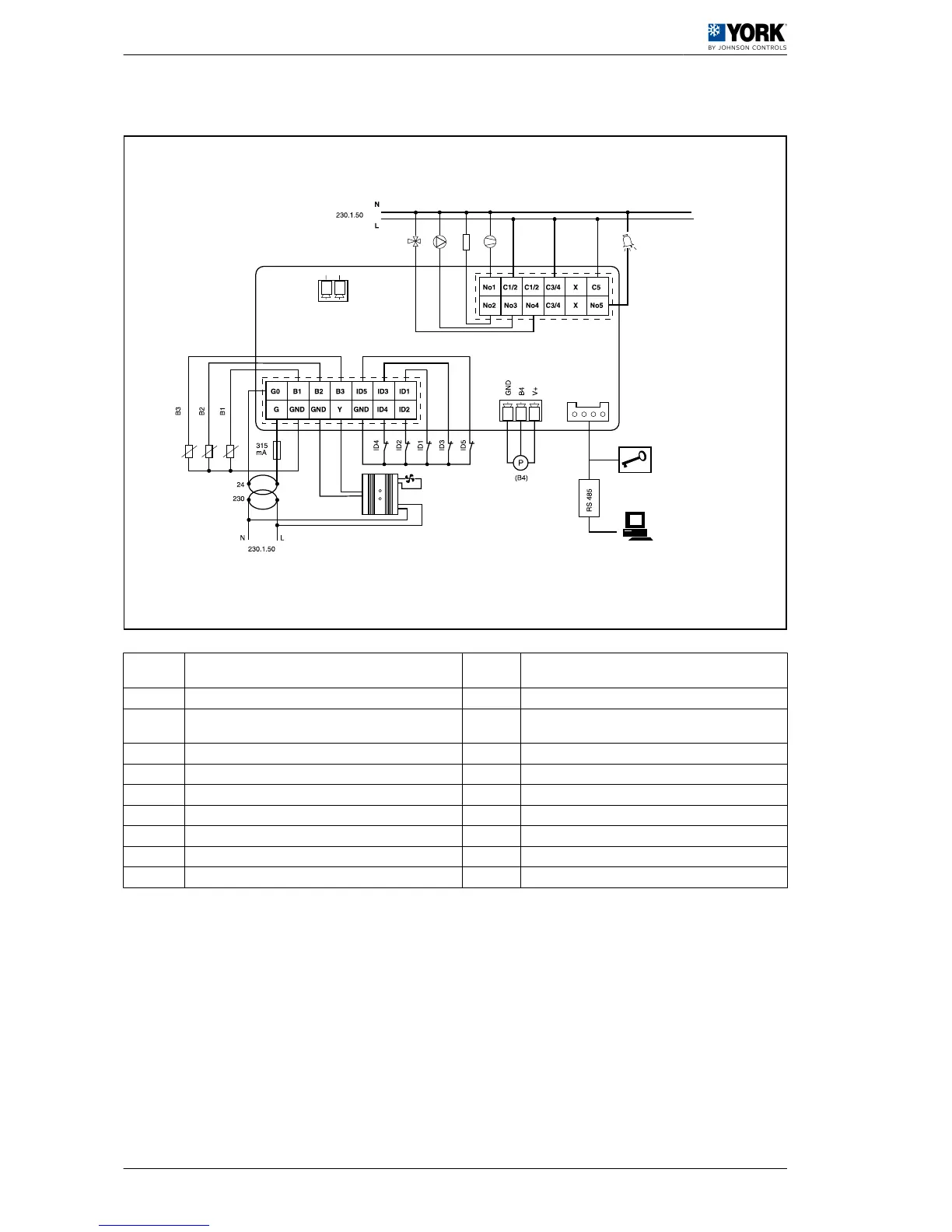
A Four-way valve B2
Water outlet temperature probe (Antifreeze pro‐
tection)
B Pump B3 Outdoor temperature probe (Dynamic set point)
C Heater B4
Ratiometric pressure probe (fan speed and defrost
control)
D Compressor 1 ID1 Water flow switch
E Alarm ID2 Remote COOL / HEAT
F 230 / 24 transformer ID3 High pressure switch
G Fan speed control ID4 Low pressure switch
H Communication ID5 Remote ON / OFF
I Programmable key N Neutral
B1 Water inlet temperature probe (Control set point) L Phase
1 User manual
1.2 Operating instructions µC2
10