5565606-TIM-B-1018
Johnson Controls Ducted Systems 11
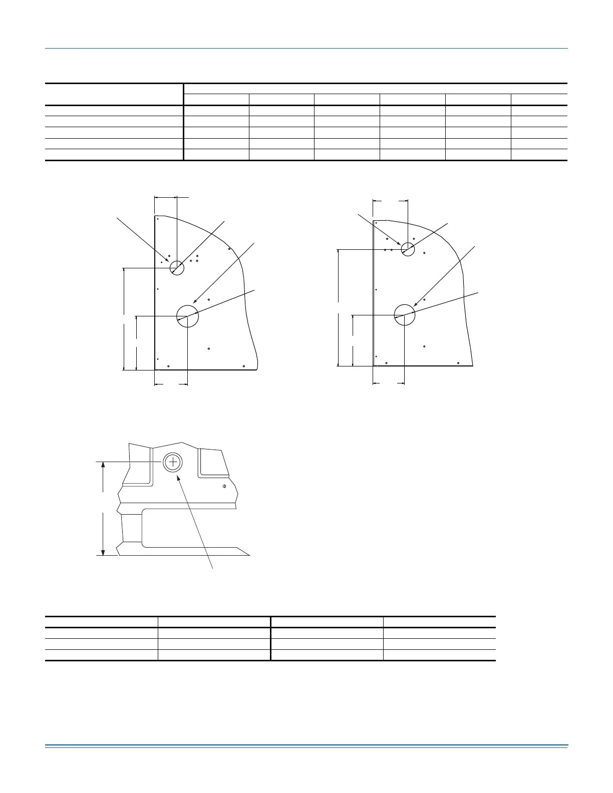
Detail A
Detail B
Table 4: ZWT06 thru T12 Unit Physical Dimensions
Unit Model Number
Dimension (in.)
ABCDEF
ZWT06 50 3/4 89 30 3/16 24 3/16 17 3/16 6 3/16
ZWT07 50 3/4 89 30 3/16 24 3/16 17 3/16 6 3/16
ZWT08 50 3/4 89 30 3/16 24 3/16 17 3/16 6 3/16
ZWT10 50 3/4 89 30 3/16 24 3/16 17 3/16 6 3/16
ZWT12 50 3/4 119 1/2 30 3/16 24 3/16 17 3/16 6 3/16
42” CABINET
Ø 3.126
Ø 2.000
3.184
4.727
7.705
14.594
Gas Pipe Inlet
Gas Exhaust Vent
50 3/4” CABINET
Ø 3.126
Ø 2.000
3.184
4.737
7.715
17.541
Gas Pipe Inlet
Gas Exhaust Vent
Table 5: ZWT06 thru T12 Unit Clearances
Direction Distance (in.) Direction Distance (in.)
Top
1
1. Units must be installed outdoors. Over hanging structure or shrubs should not obscure condenser air discharge outlet.
72 Right 12
Front 36 Left 36
Rear 36 Bottom
2
2. Units may be installed on combustable floors made from wood or class A, B or C roof covering materials.
0