5565606-TIM-B-1018
32 Johnson Controls Ducted Systems
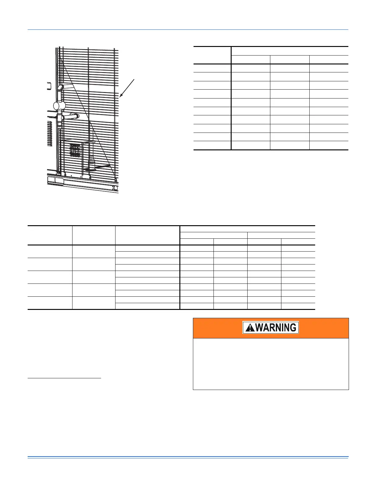
Figure 26: Bottom Entry Gas Piping
NOTE: Maximum capacity of pipe in cubic feet of gas per hour
based upon a pressure drop of 0.3 inch W.C. and 0.6
specific gravity gas.
NOTE: There may be a local gas utility requirement specifying a
minimum diameter for gas piping. All units require a 3/4
inch pipe connection at the entrance fitting. Line should
not be sized smaller than the entrance fitting size.
Gas Connection
The gas supply line can be routed within the space and roof curb,
exiting through the unit’s basepan. Refer to Figures 8 and 9 for
the gas piping inlet location. Typical supply piping arrangements
are shown in Figures 25 and 26. All pipe nipples, fittings, and the
gas cock are field supplied or may be purchased in TempMaster
accessory kit #1GP0405.
Gas piping recommendations:
1. A drip leg and a ground joint union must be installed in the
gas piping.
2. Where required by local codes, a manual shut-off valve
must be installed outside of the unit.
3. Use wrought iron or steel pipe for all gas lines. Pipe dope
should be applied sparingly to male threads only.
4. All piping should be cleaned of dirt and scale by
hammering on the outside of the pipe and blowing out
loose particles. Before initial start-up, be sure that all gas
lines external to the unit have been purged of air.
5. The gas supply should be a separate line and installed in
accordance with all safety codes as prescribed under
“Limitations”.
Table 12: Gas Pipe Sizing - Capacity of Pipe
Length of
Pipe (ft.)
Nominal Iron Pipe Size
3/4 in. 1 in. 1-1/4 in.
10 278 520 1050
20 190 350 730
30 152 285 590
40 130 245 500
50 115 215 440
60 105 195 400
70 96 180 370
80 90 170 350
90 84 160 320
100 79 150 305
Table 13: Gas Heat Minimum Supply Air
Size
(Tons)
Model Heat Size
Supply Air (CFM)
Cooling Heating
Min Max Min Max
T06
(6.5)
ZW
(N,S)12 1950 3250 1950 3250
(N,S)18 1950 3250 1950 3250
T07
(7.5)
ZW
(N,S)12 2250 3750 2250 3750
(N,S)18 2250 3750 2250 3750
T08
(8.5)
ZW
(N,S)12 2550 4250 2550 4250
(N,S)18 2550 4250 2550 4250
T10
(10)
ZW
(N,S)18 3000 5000 3000 5000
(N,S)24 3000 5000 3000 5000
T12
(12.5)
ZW
(N,S)18 3750 6250 3750 6250
(N,S)24 3750 6250 3750 6250
Natural gas may contain some propane. Propane is an
excellent solvent and will quickly dissolve white lead and
most standard commercial compounds. A special pipe
dope must be used when assembling wrought iron or
steel pipe. Shellac based compounds such as Gaskolac
or Stalastic, and compounds such as Rectorseal #5,
Clydes’s or John Crane may be used.