EN.
34
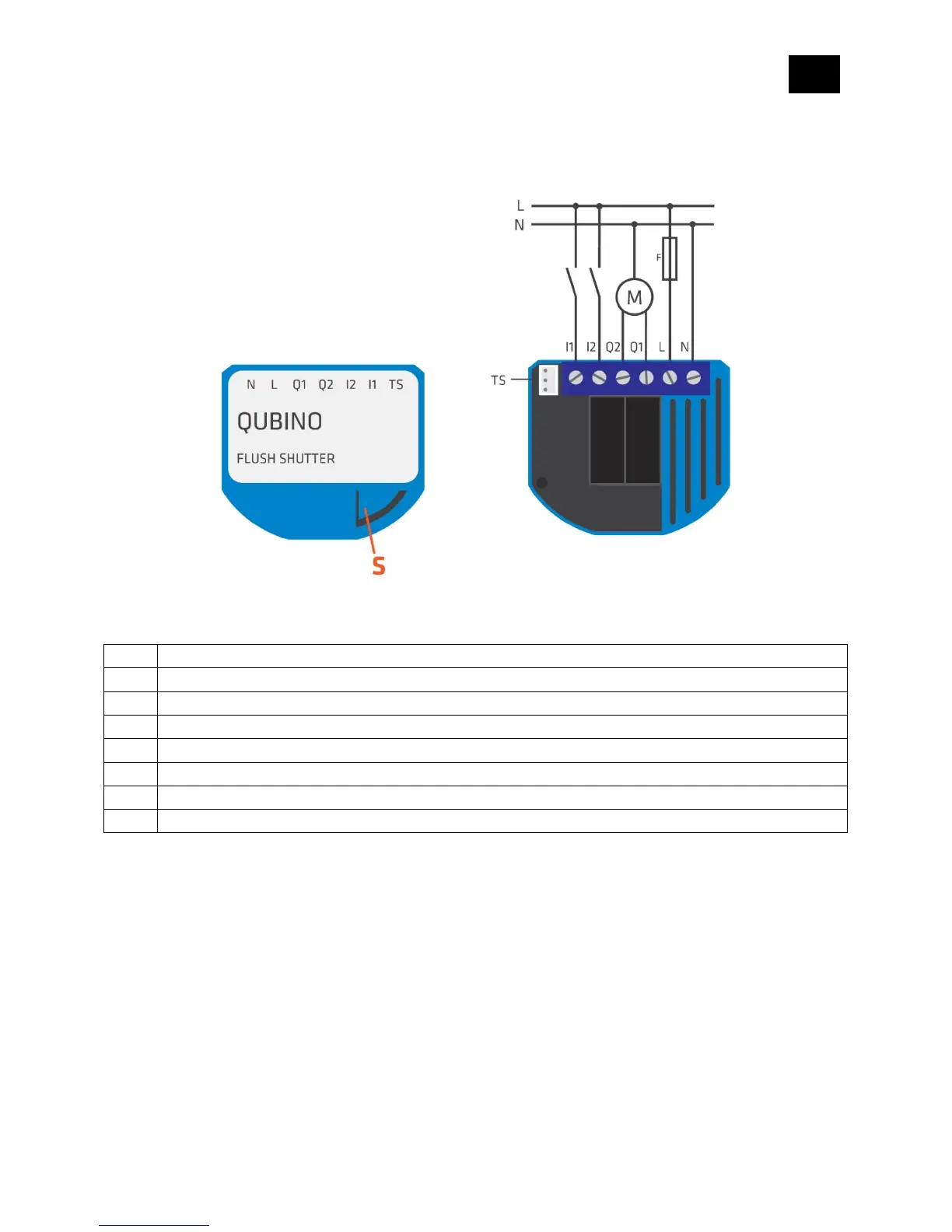
9. Electrical Diagram (110 - 230VAC, 24VDC)
Notes for diagram:
Output for motor UP (open)
Output for motor DOWN (close)
Input for switch/push button DOWN (close)
Input for switch/push button UP (open)
Temperature sensor terminal
WARNING:
The S (Service) button must NOT be used when the device is connected to a 110-230V power supply.
The durability of the device depends on the applied load. For resistive loads (light bulbs, etc.) and 4A current
consumption of each individual electrical device, the product’s lifespan exceeds 70,000 toggles.
OVER CURRENT PROTECTION
When the current exceeds 4A, relay is automatically turned off and “Over-current detected” Notification will also
be sent to the gateway. To reactivate the module, the power supply has to be turned OFF and ON again.