B
C
A
E
D
B
C
D
A
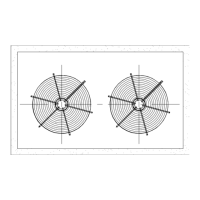
SPREADER BAR
NOMINAL PIPE THRU UNIT FOR SLINGS TO AVOID BASE DAMAGE.
END
PROPER CLEARANCE TO BE
PROVIDED.
COMPRESSOR
LIFT
LIFT
2. PIPE DIA 2" FOR PT090 TO PT360 MODELS
1 .PIPE DIA 1 1/2" FOR PT036 TO PT075 MODELS
Note:
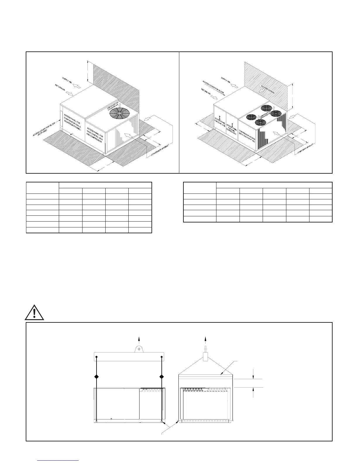
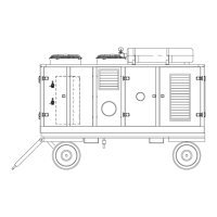
SERVICE CLEARANCE
MODEL DIMENSIONS
NUMBER A B C D
PS036 85 105 85 150
PS048 85 105 85 150
PS060 85 105 85 150
PS075 90 105 90 200
PS090 90 105 90 200
PS100 90 105 90 200
PS120 90 105 90 200
NOTE: All dimensions are in cm.
A :Clearance dimension from condenser coil
B :Clearance dimension from compressor, control box, blower, evaporator coil & filter
C :Clearance dimension from condenser coil & filter
D :Clearance dimension over the condenser fan
MODEL DIMENSIONS
NUMBER A B C D E
PS180 120 120 115 250 90
PS215 120 120 115 250 90
PS240 120 120 115 250 90
PS300 120 120 115 250 90
PS360 120 120 115 250 90
A : Clearance dimension from condenser coil
B : Clearance dimension from compressor, control box & evaporator coil
C : Clearance dimension from condenser coil & blower
D : Clearance dimension over the condenser fan
E : Clearance dimension from filter access panel
MODELS: PS036 - PS120
MODELS: PS180 - PS360
ATTENTION TO RIGGERS
• Insert 2" nominal pipe through holes in the base rail as shown in the figure below for slings.
• Holes in base rail are centered around the unit center of gravity.
• Use wooden pallet or spreader bar when rigging, to prevent the slings from damaging the unit.
• Rollers may be used to move the unit on the roof or ground.
CAUTION: All panels should be in place when rigging.
RIGGING INSTRUCTIONS
MODELS: PS036 - PS360
NOTE: Only two condenser fans for models PS180 - PS240.
5