AEMZP0BA - EPS-AC0 - User Manual Page - 39/95
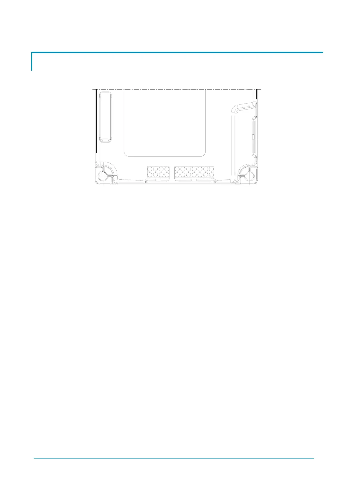
9.1 Connectors of the logic
CNC
1
8
85
4
1
8
1
7
14
CNB CNA
Figure 9–2
9.1.1 CNA connector
A1 DRIVE SWITCH Traction Travel Demand Input.
A2 SW2 2
nd
Toggle Switch or Left Limit Switch (LLS).
A3 SW1 1
st
Toggle Switch or Right Limit Switch (RLS).
A4 NK1 Safety Switch Lower Voltage Point.
A5 K1 Safety Switch Higher Voltage Point.
A6 CANL Can Bus Low.
A7 KEY Key in (24-36 Vbatt).
A8 CPOC2 / QL 2
nd
SP POT Wiper or Stepper Motor Q line.
A9 CPOC1 / DL 1
st
SP POT Wiper or Stepper Motor D line.
A10 NPOC Twin SP POT Negative Supply (GND).
A11 GND GND. Encoder Negative Supply
A12 GND GND. SW1 & SW2 Negative.
A13 GND GND. Motor Thermal Sensor Negative.
A14 CANH Can Bus High.
9.1.2 CNB connector
B1 NPOT FB POT Negative Supply.
B2 PPOT FB POT Positive Supply.
B3 THMOT Motor Thermal Sensor (KTY84-130) Input.
B4 +5VDC Encoder Positive Supply.
B5 PPOC Twin SP POT Positive Supply (5 Vdc).