Head-Up Sensor Replacement 980358-408A
Preparations
Protect against static discharge. Your work area must be static-safe and include
a properly grounded conductive cushioned mat to hold the printer and a
conductive wrist strap for yourself.
Perform the removal steps of the Bottom Case Replacement procedure (980358-405).
Removal
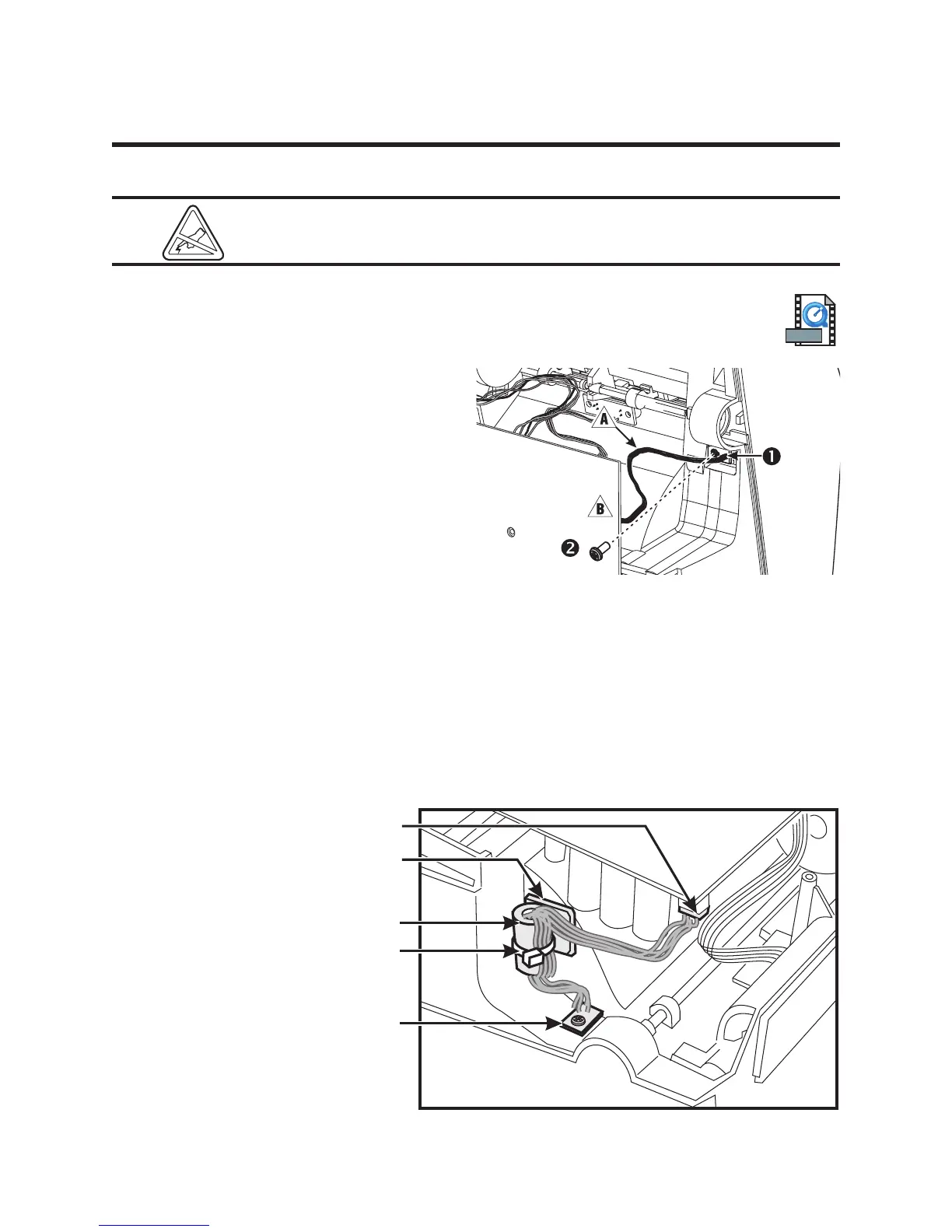
1. Unplug the ribbon cable ! from the sensor
1 where it attaches to the main PCBA
".
Note its location.
2. Use a #1 Phillips to remove the screw 2
that holds the sensor to the bottom of the
media frame. Cut away any tie-wrap.
Assembly
1. Align the sensor so that its ribbon cable is to the left; then, place it one the bottom of the media
frame.
2. Replace the screw that holds the sensor to the frame; then, use a #1 Phillips driver to tighten it.
3. Plug the ribbon cable from the sensor into its connector on the main PCBA.
New head-up sensors include a ferrite-core and a tie-wrap and anchor to secure the ribbon cable to
the frame.
Assembling the Printer
Perform the assembly
steps of the Bottom Case
Replacement procedure
(980358-405). Check the
installation. Turn on the
printer and run the
AutoSense routine to get a
dump mode printout.
This action tests the
printer's media drive and
printing capabilities.
32 980358-001 Rev. B
MOVIE
Main PCBA
Ferrite
Core
Head-Up
Sensor
Connector
Motor
Tie-Wrap
Anchor
Adjustment
Knob
Media
Guide