Real Time Clock Option 980358-418A
Preparations
Protect against static discharge. Your work area must be static-safe and include
a properly grounded conductive cushioned mat to hold the printer and a
conductive wrist strap for yourself.
Perform the removal steps of the Bottom Case
(980358-405) and Main PCBA (980358-409)
replacement procedures.
Installation
The socket for the real-time clock option is
designated as U15 on 2443 printers, U24 on
both TLP and LP2844 printers.
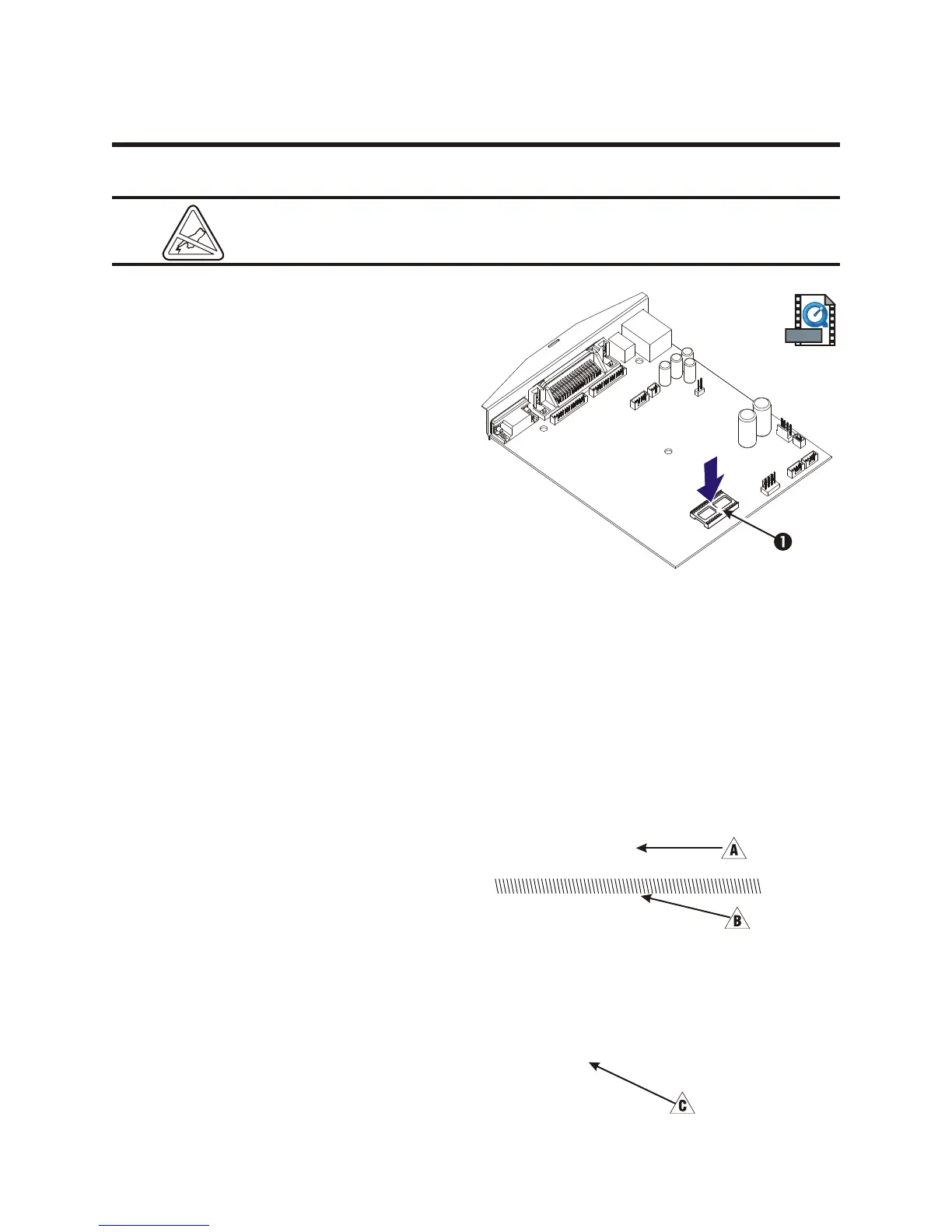
1. Align the real time clock chip above its
location on the main PCBA 1. Make sure
the notched end of the chip is oriented
correctly to the outline on the board.
2. Lower the real time clock chip into place taking care not to bend any of the pins.
Assembling the Printer
Perform the assembly steps of the Main PCBA (980358-409) and Bottom Case (980358-405)
replacement procedures.
Checking the Installation
Turn on the printer and run your printer's AutoSense rou tine to get a dump mode
print out. This ac tion tests the printer's
me dia drive and print ing ca pa bil i ties.
980358-001 Rev. B 43
8” UKQ1775 V3.20
Serial port : 96,N,8,1
Image buffer size:0507K
Fmem:000.5K,060.9K avl
Gmem:024K,0045K avl
E
I8,0,001 rN
S4 D10 R064,000 ZT UN
q1600 Q1209,026
Option:
17 21 25
Date: 07-19-99
Time: 12:44:00
now in DUMP
mem:000K,0045K avl
You can also check the print out.
! Firmware version number
" Memory (available bytes)
# Real time clock option (when installed)