2
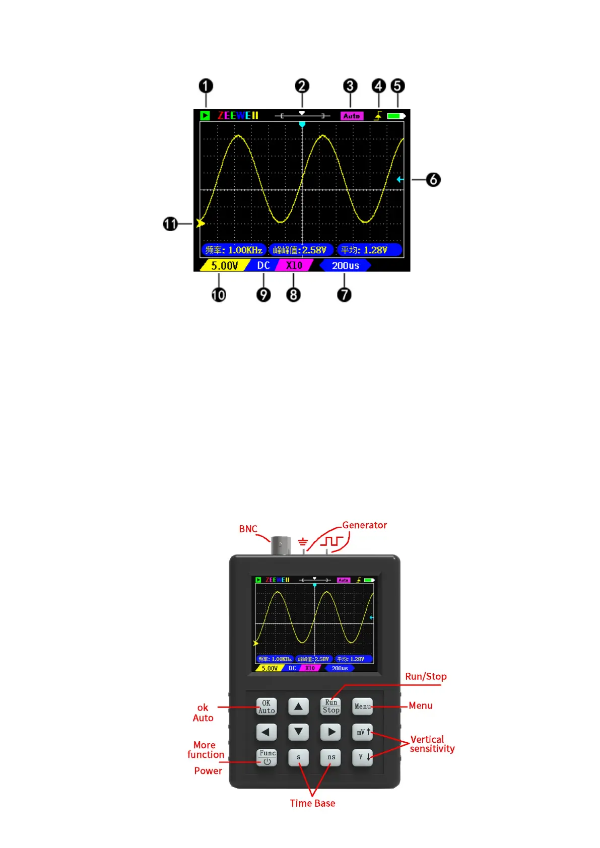
① Green is the ‘Run’ state; Flashing cyan for waiting to trigger; Red is ‘Stop’.
② The horizontal line is the sample memory, and the box is the display area.
③ Auto indicates that the trigger mode is ‘Auto’. Normal indicates that the trigger
mode is ‘Normal’.
④ Trigger edge: Rising edge trigger or falling edge trigger.
⑤ Battery level indication.
⑥ Trigger level position.
⑦ Timebase: The time of a grid.
⑧ X1/X10 indicates probe attenuation, which should be set to match the probe. The
goal is to tell the oscilloscope what attenuated probe you used.
⑨ DC/AC coupling.
11. Vertical sensitivity: Indicates the voltage of a grid.
12. Zero arrow: The baseline position, where the vertical voltage is zero.
Buttons Function