2
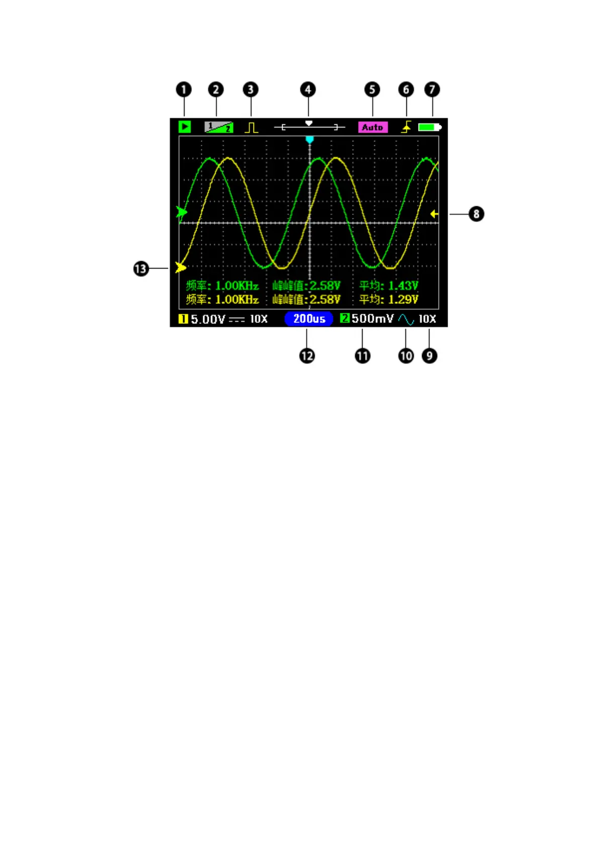
① Green is the running state; Flashing cyan for waiting to trigger; Red is stopped.
② Channel priority: Yellow 1 indicates that CH1 has high priority, and the CH1
waveform can be moved up or down.
③ Yellow: Turn on the signal generator output; Gray: Turns off the output.
④ Shows the position of the current time base window in memory.
⑤ Auto indicates that the trigger mode is automatic. Normal indicates that the trigger
mode is normal.
⑥ Trigger edge: Rising edge trigger or falling edge trigger.
⑦ Battery level indication.
⑧ Trigger level position.
⑨ X1/X10 indicates probe attenuation, which should be set to match the probe. The
goal is to tell the oscilloscope what attenuated probe you used.
⑩ DC/AC coupling.
⑾ Vertical sensitivity: Indicates the voltage of a grid.
⑿ Timebase: The time of a grid.
⒀ Zero arrow: The baseline position, where the vertical voltage is zero.
Note: (CH2 icon is gray to indicate that it is off, if you do not need to test two signals
at the same time, please close CH2 to obtain higher sampling rate and reduce power
consumption).