13
dashed lines. The vertical (voltage) cursor can only measure one channel, and
whichever channel has the highest priority, measure the voltage of which channel.
8 Menu introduction
8.1 Channel
The channel menu includes two options, "Coupling" and "Probe".
The coupling can be set "DC coupling" and "AC coupling". DC coupling passes
the signal directly. AC coupling is equivalent to series connection with the capacitor.
Probes are available in " 1X" / "10X"/ "100X", this option corresponds to the
oscilloscope probe. When the probe is switched to the 10X position, this option
should be selected as " 10X". The same goes for the 1X.
8.2 Measurement
There are 14 measurement options available, as shown below:
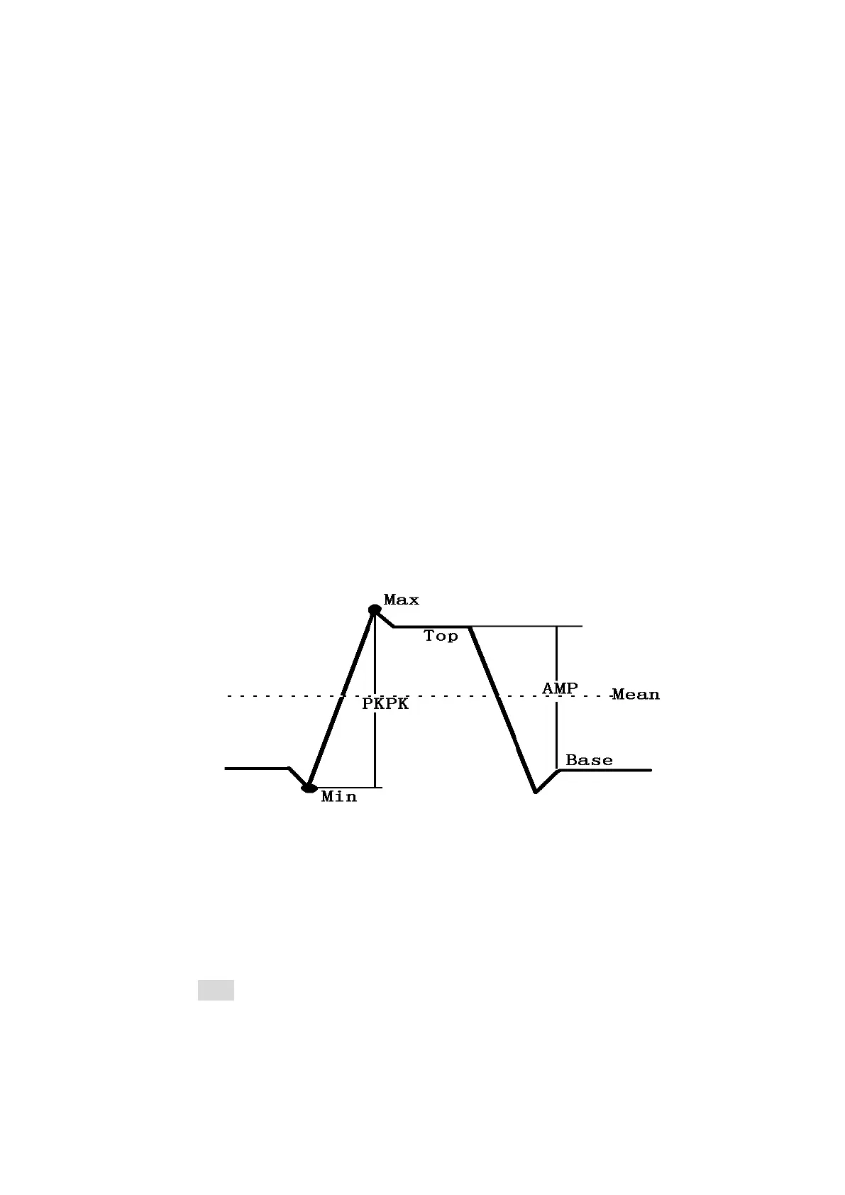
Frequency, Peak-to-Peak, Duty cycle, Amplitude, RMS, Average, Period, +Pulse
width, -Pulse width, Max, Min,Top, Base, -Duty cycle.
The difference between peak-to-peak and amplitude(AMP) is shown in the
figure above.
8.3 Trigger
There are four options in the trigger menu: “Trigger Mode” ,“Trigger Type” ,
“Trigger level”and “Trigger source”.
Trigger Mode can be selected from "Auto" and "Normal".
For “Auto” mode, if a waveform trigger is detected, the waveform will be used
for triggering. At this time, the waveform can be displayed stably. If the oscilloscope
cannot detect the trigger condition, it will automatically force the trigger to display the
waveform, but because there is no suitable trigger condition, the waveform will not be
displayed steadily.