HDS4x2 User Guide, Rev 1.1, 08-31-07
2
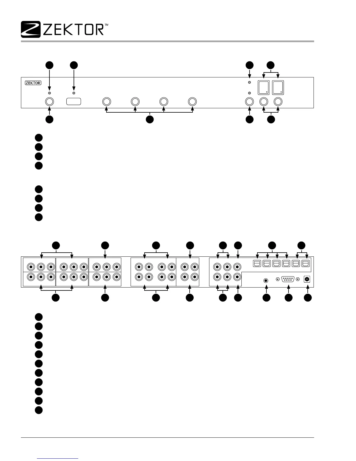
Overview of the HDS4x2
Front panel controls
Most functions of the HDS4x2 can be done using front panel controls. The controls are dened as:
1
Power toggle button.
2
Input selection buttons 1 - 4.
3
Breakaway selection button.
4
Zone selection buttons 1 & 2.
Status LED indicators are dened as:
5
Standby mode indicator, lit when in standby mode.
6
IR indicator, ashes when an IR code is received.
7
Current audio / video breakaway selection.
8
Current input mappings for each zone (1 & 2).
Rear Panel Connections
IN-1IN-3
IN-2IN-4
OUT-1
ANALOG AUDIO INPUT
ANALOG AUDIO OUTPUT
DIGITAL AUDIO
OUT-2
RS232 9VDC
IR-IN
Y/G Pb/B Pr/R Y/G Pb/B Pr/R Y/G Pb/B Pr/R
Y/G Pb/B Pr/R Y/G Pb/B Pr/R Y/G Pb/B Pr/R
IN-1
R IN-1 L R IN-2 L
R IN-3 L R IN-4 L
R OUT-1 L IN-1 IN-2 OUT-1
IN-3 IN-4 OUT-2R OUT-2 L
IN-2 IN-3 IN-4 OUT-1 OUT-2
Rear panel connections are dened as:
1
Component video inputs. Accepts component Y/Pb/Pr or RGB with sync on green.
2
Component video outputs.
3
Analog audio inputs.
4
Analog audio outputs.
5
Digital audio coax inputs.
6
Digital audio coax outputs.
7
Digital audio optical inputs.
8
Digital audio optical outputs.
9
IR jack.
10
RS-232 serial connector.
11
Power connection. Center connector is positive (+).
1 43
21
2
3 4 5
5 9 10 11
7 8
6
6
1 43
21
2
3 4 5
5 9 10 11
7 8
6
6