26
3. REASSEMBLY OF MIXER PARTS
3.1 Reassembly of the drive type 481.0000
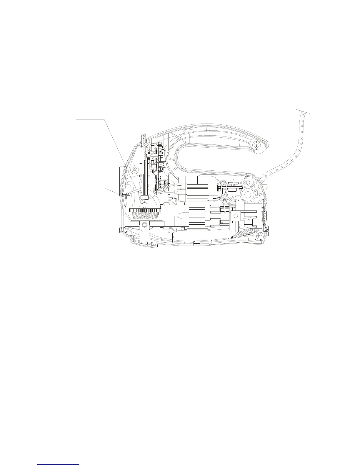
The reassembly of the drive is carried out in the reverse order to its disassembly. The
layout of the parts and correct arrangement of the internal wires are shown in Fig. 6, Fig.7 and
Fig.8.
Fig. 6
During the reassembly, take special care when placing the elastic arm of the pusher 4 on the
shelf of the mixer’s right housing (Fig. 6).
All soldered connections should be made carefully with the wire ends bent into hooks. Arrange
the wires in the grooves in such a manner as to avoid stress in the internal connections or their
contact with the movable parts.
Solder the internal wires 13, 14, 15 into the catches of the switch, and place them in the slit of
the switch plate according to Fig. 7. Then, place the switch in the mixer housing, and arrange
the wires in the recess of the housing rib. Lead the internal wires so that they will not come into
the zone of shock absorber sockets.