28
3.3 Reassembly of the stand with balance type 481.1500
In the first place, carry out the reassembly of the stand with balance type 481.1000,
without fitting the supports 13 (Fig. 4). Given below are additional guidelines for the correct
reassembly of the stand with balance. Fit the supports 13 in the scale base prior to starting the
assembly of the remaining elements.
Grease the interlock fork 16 with white petrolatum in the places of their contact with the
interlock knob 17, metal covers 21, scale base 15 and base 1.
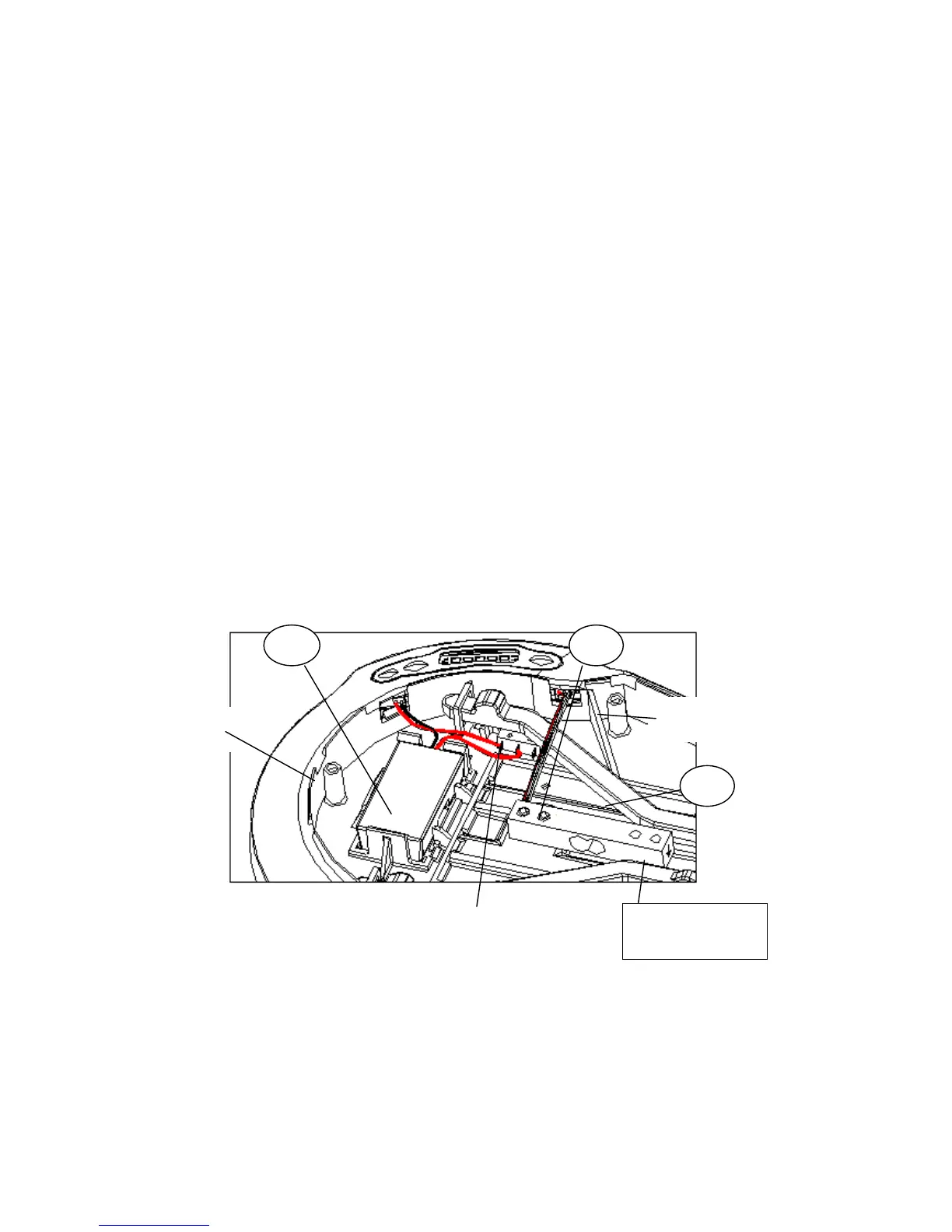
Grease the rotary connection of the interlock knob 17 with the scale base 15 (take special care
to correctly connect the wires from the battery container 23 and sensor cpl. 22 to the electronic
plate together with a display 24 according to Fig. 8).
Pay special attention to the correct assembly direction of the sensor beam according to the
sticker located on the beam face and Fig. 8.
Arrange the wires of the sensor cpl. 22 above the interlock fork 16, taking care not to pull them
off during the reassembly (for the correct operation of the balance the gap between the scale
base 15 and the base 1 must be retained).
When fitting the scale base 15 onto the base 1 use the three basis holes (two of them are
shown on Fig. 8) through which the basis pins Ø5 are to be inserted into the respective holes
of the base 1.
Remove the basis pins Ø5 after tightening the screws 28 with the spring washers 25.
Place two batteries (1.5 V, type AA) in the battery container 23, paying attention to their
polarity and snap the battery cover 18. Glue the new decorative foil 20, when required.
Fig. 8
After reassembling the Stand with balance, check to make sure that when the interlock knob is
turned to the OFF position the balance is disconnected and the stand locked relative to the
scale base, and then check to make sure that when the knob is in the ON position the balance
works properly (follow the instructions provided in the user manual).