19
Once you have soldered all the leads, check the rigidity of the solder joints by flipping the switch
several times. Make sure it feels secure.
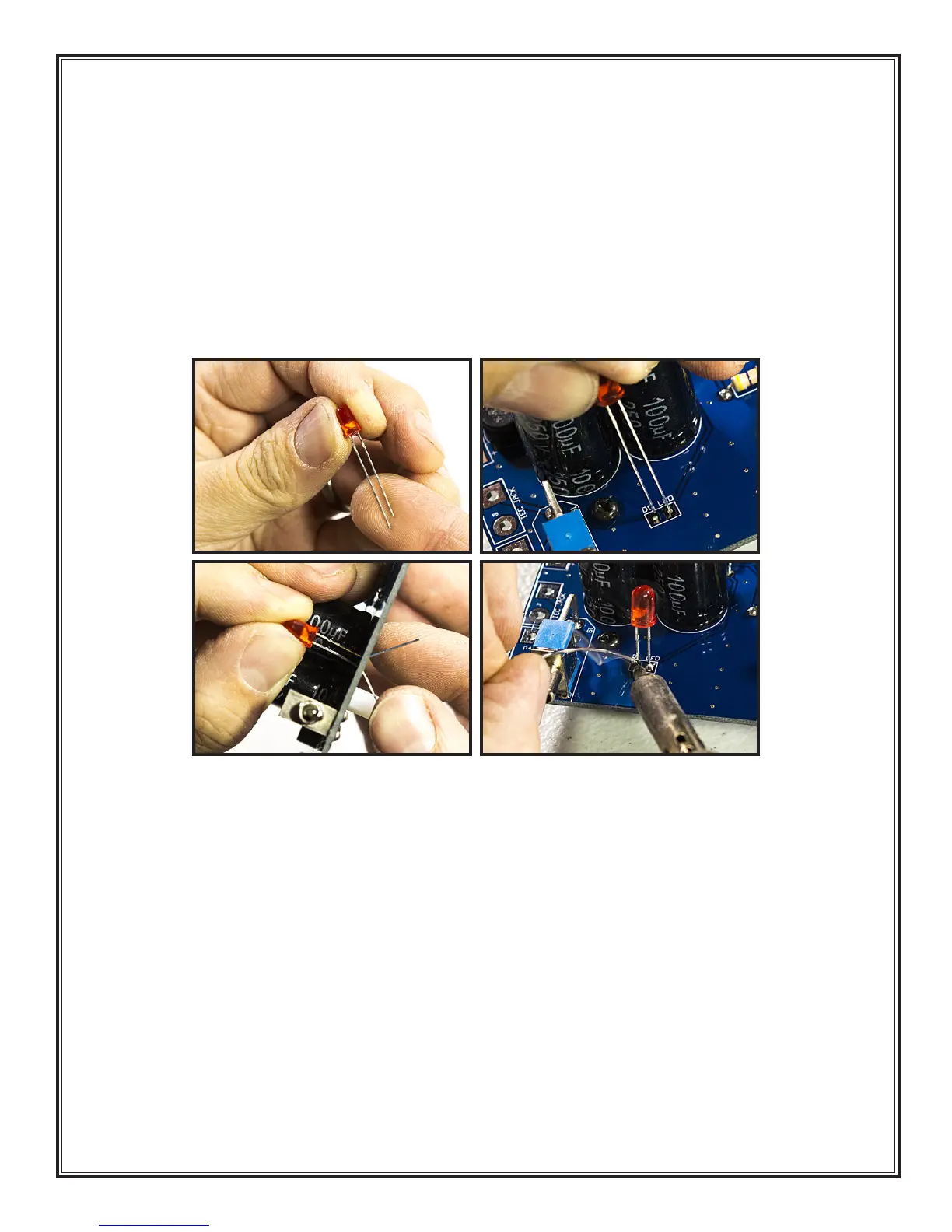
10. LED (Part # D1): The LED (light emitting diode) is a polarized component, meaning that it matters
which way it goes into the holes. Following the standard of all the polarized components on this
board, the long lead goes into the square hole.
30, 31
If you do not install the LED in the correct
orientation the “on light” will not work. Install the LED in the holes so that the top of the LED stands
about 7/8” (23mm) off the surface of the board.
32
Solder the LED on the component side of the
board (it will be easier to switch later if you get it backwards).
33
Clip the leads on the solder side
of the board.
11. Feedback loop wire (Part # CB10.1): Strip about 1/4” (6mm) of insulation from each end of the
10.5cm single stranded hookup wire.
34
Solder one end of this wire to the FBL hole so the wire is
emerging from the component side of the board.
35, 36
The other end of the wire will be used in
the next section.
30 31
32 33