12
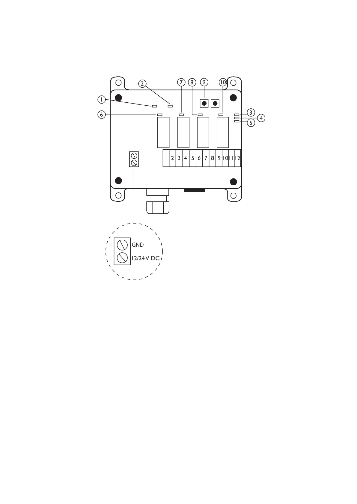
7. Circuit card - 4 channel radio.
Circuit card: explanation
1. Yellow LED indicates correct voltage.
2. Green LED indicates receiving of radio signal.
3. Red LED off = no transmitter programmed.
Red LED blinks = transmitter programmed.
Red LED shines = receiver in program mode.
4. Not in use.
5. Not in use
6. Indicates that UP function is activated (shine when button is pushed)
7. Indicates that TILT function is activated (shine when button is pushed)
8. Indicates that DOWN function is activated (shine when button is pushed)
9. In use at programming new transmitter
10. Indicates that LOCK function is activated