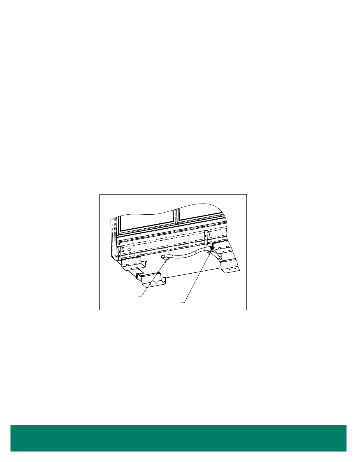
DRAIN LINE
The drain is located at the center of the case in the oor pan. The drain can be reached by removing the center coil covers and then
removing a fan motor. The 1" PVC drain outlet is located at the center front of the case behind the kickplate.
Install the tee to the outlet pipe and a drain trap to the tee. Plug the open end of the tee using the clean-out plug supplied with the drain
trap kit. The drain line must be pitched away from the case. The tee, drain trap and plug are supplied with the case. The factory installs
a drain support at the front of the case on all 30" door cases. We supply a trap support that is eld mounted to the case (Figure 15). The
drain trap must be level. The drain trap should be primed with water after installation. The drain line must be pitched away from the case
enough to insure proper drainage. Consult your local codes for minimum requirements.
Drain Support
Drain Trap Support
DWG NO.SP-6000-1REV. B
TOLERANCES:
(PER SP-0457)
(NONE)
RELEASED
PART WEIGHT:
(IN LBS)
CAD DRAWING
NO MANUAL REVISIONS
COPYRIGHT INFORMATION
THIS DRAWING AND THE INFORMATION CONTAINED WITHIN, IS
THE SOLE PROPERTY OF ZERO ZONE, INC. ANY USE OF THIS
DOCUMENT OR DISCLOSURE OF ITS CONTENTS; BY
REPRODUCTION OR OTHER MEANS, WITHOUT THE WRITTEN
CONSENT OF ZERO ZONE, INC. IS STRICTLY PROHIBITED.
(NONE)
(NONE)
FINISH:
(PER SP-0154)
MATERIAL:
(PER SP-0404)
(UNLESS OTHERWISE SPECIFIED)
A
SHEET
SIZE
NOT TO SCALE
JZ
SCALE:
MODELED BY:
DRAWN BY:
UNLESS OTHERWISE
SPECIFIED, ALL DIMENSIONS
ARE IN DECIMAL INCH
9/10/2012
B
1 OF 1
SP-6000-1
DRAIN TRAP
SHEET:
DATE:
REVISION
ZERO ZONE, INC.
110 NORTH OAKRIDGE DRIVE
NORTH PRAIRIE, WISCONSIN
USA 53153
DRAWING No:
DESCRIPTION:
BY
DATE
ECN No.
REVISION DESCRIPTION
No.
JZ
9/10/2012
9651
REVERSE DRAIN DIRETCTION
B
REVISION INFORMATION
Figure 15: Trap Support
16 • Drain Line