LINEUP ASSEMBLY
Zero Zone display cases have been engineered for continuous display. This means that any number of cases can be joined together to
create a display of any desired length. The bottom of the end panel is protected with a removable steel plate.
The lineup is assembled by sliding one case up to the second case and then bolting the cases together. Bolt holes for the bottom of the
frame can be accessed by removing the right and left coil covers. The front and top bolt holes are visible on the steel end frame. The rear
bolt holes are exposed by removing the lift-out duct on the 30" door cases and by removing pocket covers on the 24" door cases. Figure
12 on page 13 show the bolt hole locations for each case. Bolt kits and instructions are supplied with the case.
Figure 9 gives instructions on applying caulk to the case joint before the cases are slid together. Once the cases have been caulked and
slid together, start the joining bolts, but do not tighten them. Slide the t-strip between the door frames (Figure 11 on page 13). Begin
tightening the bolts at the top rear, working down the back of the case and up the front, making sure that the front seams are ush. Bolts
are not designed to pull the cases together.
Two different model cases or two different temperature cases are connected using an insulated divider. Typically the divider is factory
assembled to one of the cases. Two styles of divider are provided. The rst style has a panel on each side with nut inserts in the panels.
Each side is bolted to the end frame. Instructions for assembly of this style are given in Figure 13 on page 14. The second style
divider uses a thru-bolt design. The divider is attached to one of the cases using short bolts. When the case is installed, the short bolts
are removed and long bolts are reinstalled to bolt both cases together. Instructions for assembly of this style case are given in Figure 14
on page 15. Bolts are not designed to pull the cases together.
For NSF case installation, the interior case seams need to be sealed using NSF approved caulk (not supplied) as shown in Figure 10 on
page 13.
The end panel protector support plates should be removed after the cases are set in their nal position.
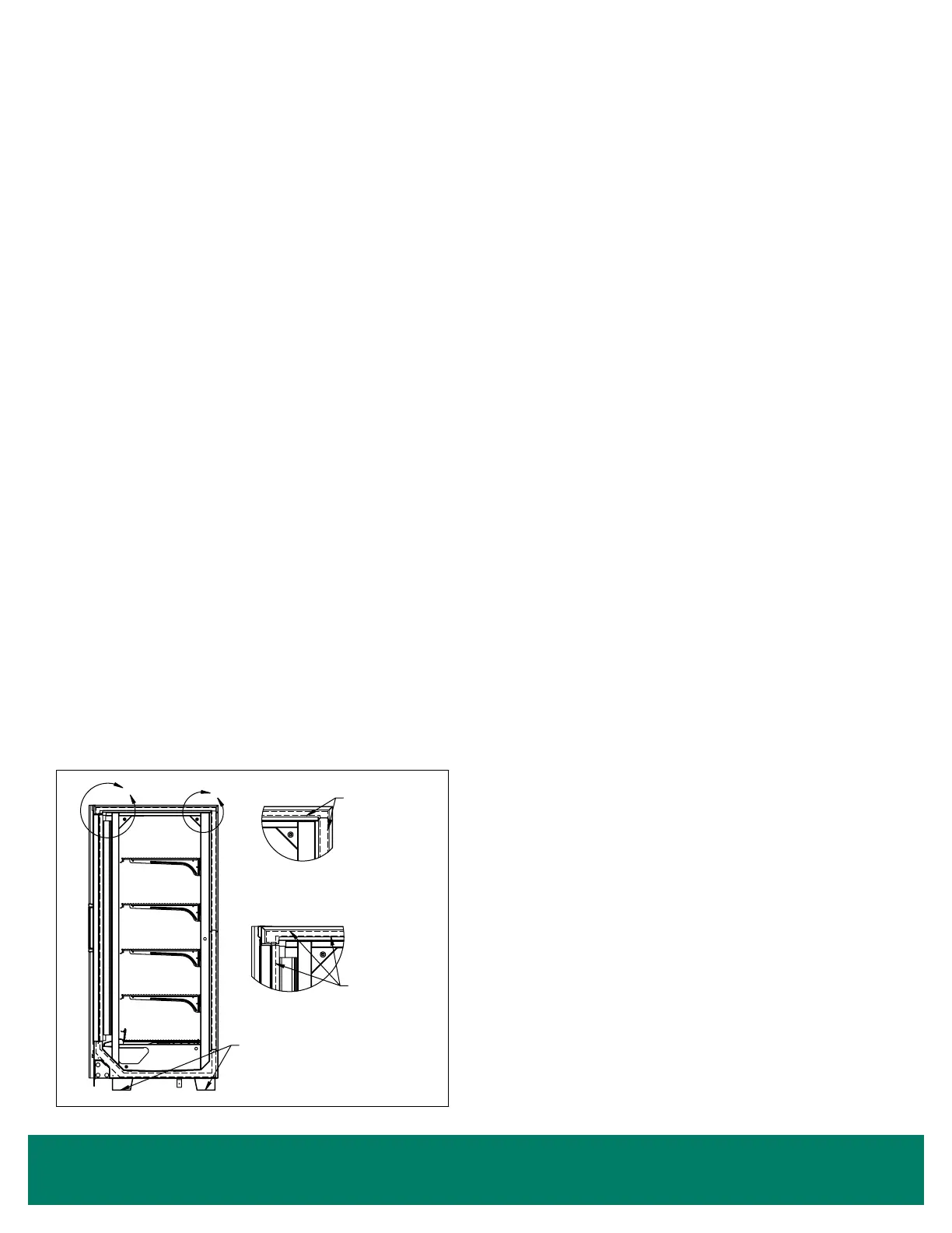
Figure 9: Caulking Cases to be Joined
DO NOT APPLY EXCESS AMOUNTS OF BUTYL SEALANT THAT WOULD CAUSE IT TO SQUEEZE ONTO END FRAME
METAL AREAS. Caulk sealant used to join cases and complete the sealing requirements for NSF compliance should not come
in contact with butyl sealant. Apply to clean, dry surfaces free of contaminants that adversely affect adhesion and could change
color of sealant joint areas over time.
PROCEDURE FOR JOINING CASES
These procedures are critical! Failure to follow these guidelines
will result in a poorly functioning case. This is especially true of
low temp cases.
1. Apply two ¼" to 3/8" wide beads of butyl sealant, ½" in from
the inside and outside edges of foamed insulated ceiling, rear
wall, base, and door frame to be joined. Apply to only one
case joint to avoid excessive amounts of butyl sealant that
would squeeze out of the joint. Sealant is not applied to the
structural steel end frames. After cases are joined, caulk the
top and back exterior seams (if possible) at this time.
2. When joining ends of cases, caulk sealant should be applied
in the same manner for joints.
A
B
Remove (4) Filler Blocks If
Applied To Inside Of Base
Ends Before Joining Cases
DETAIL A
DETAIL B
1/4" - 3/8" Typ.
Butyl Sealant
Beads
1/4" - 3/8" Typ.
Butyl Sealant
Beads
DWG NO.SP-6005-1REV. B
TOLERANCES:
(PER SP-0457)
(NONE)
RELEASED
PART WEIGHT:
(IN LBS)
CAD DRAWING
NO MANUAL REVISIONS
COPYRIGHT INFORMATION
THIS DRAWING AND THE INFORMATION CONTAINED WITHIN, IS
THE SOLE PROPERTY OF ZERO ZONE, INC. ANY USE OF THIS
DOCUMENT OR DISCLOSURE OF ITS CONTENTS; BY
REPRODUCTION OR OTHER MEANS, WITHOUT THE WRITTEN
CONSENT OF ZERO ZONE, INC. IS STRICTLY PROHIBITED.
(NONE)
(NONE)
FINISH:
(PER SP-0154)
MATERIAL:
(PER SP-0404)
(UNLESS OTHERWISE SPECIFIED)
A
SHEET
SIZE
NOT TO SCALE
JZ
SCALE:
MODELED BY:
DRAWN BY:
UNLESS OTHERWISE
SPECIFIED, ALL DIMENSIONS
ARE IN DECIMAL INCH
9/13/2012
B
1 OF 1
SP-6005-1
JOINING CASES
SHEET:
DATE:
REVISION
ZERO ZONE, INC.
110 NORTH OAKRIDGE DRIVE
NORTH PRAIRIE, WISCONSIN
USA 53153
DRAWING No:
DESCRIPTION:
BY
DATE
ECN No.
REVISION DESCRIPTION
No.
JZ
9/13/2012
9651
UPDATE CASE VIEW
B
REVISION INFORMATION
12 • Lineup Assembly