111
HYDRAULIC SYSTEM
F_02_H10 F_02_H14
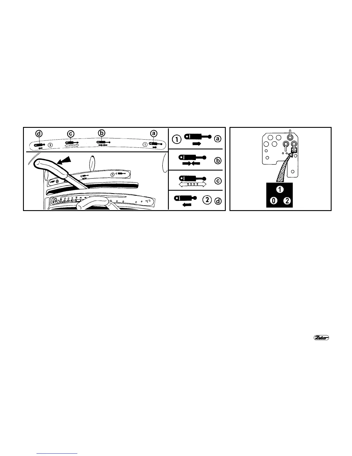
OUTER CIRCUIT CONTROL LEVER - HYDRAULIC WITH MECHANICAL CON-
TROL SYSTEM
Control lever has three positions marked on label.
a -
Pressure is in quick-coupler No "1", quick-coupler No "2" is connected with
return line. Lever is moved into its rear margin position. The lever must be
kept in this position otherwise it is automatically turned into neutral position
"b".
b -
Neutral position (locked). Outlets of quick-couplers No "1" and "2" are closed
and the oil is blocked in attached hydraulic implement. The lever is automati-
cally kept by spring in this position.
c -
Floating (free) position. Both outlets of quick-couplers No "1" and "2" are con-
nected with return line and the oil can freely flow in both directions. Lever is
locked by valve ball lock in this position.
d -
Pressure in quick-coupler No "2", quick-coupler No "1" is connected with re-
turn line. Lever is moved into its forward margin position. lever must be kept
in this position otherwise it is automatically turned into floating position "c".
REAR OUTLETS OF HYDRAULIC
OUTER CIRCUIT
In basic version the outlets of hydraulic
outer circuit are equipped with three
quick-couplers. Quick-couplers No "1"
and No "2" are pressurized. Pressure is
in particular quick-coupler depending
upon position of outer circuit control
lever. The third quick-coupler No "0" is
connected directly with differential case
space and is intended for turning the oil
from hydraulic implements (for example
from rotary hydro-motors etc.).
Location of quick-couplers corresponds
with tractor hydraulic equipment without
SCV.
 Loading...