Quick Installation Guide
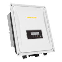
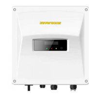
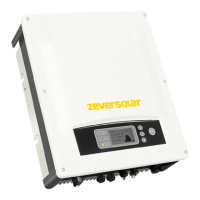
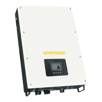
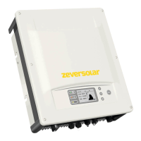
Zeverlution 1000S
Zeverlution 1500S
Zeverlution 2000S
Zeverlution 3000S
1.1 Intended Use
1) Zeverlution is a transformerless photovoltaic (PV) inverter with one MPP tracker which converts the direct
current of the PV array into grid-compliant alternating current, and feeds it into the utility grid.
2) The product must only be operated by qualified persons with the appropriate skills who have already read
all documentation relating to its installation, commissioning, operation and maintenance.
3) The product is suitable for indoor and outdoor use.
4) The product must only be operated with PV arrays of protection class II in accordance with IEC 61730,
application class A. Do not connect any sources of energy other than PV modules to the inverter.
5) PV modules with a high capacity to ground must only be used if their coupling capacity is less than 1.0μF.
6) When exposed to sunlight, the PV array generates dangerous DC voltage which is present in the DC
conductors and the live components of the inverter. Touching the DC conductors or the live components
can lead to lethal electric shocks.
7) The product is also approved for the Australian market and may be used in Australia. If DRM support is
specified, the inverter may only be used in conjunction with a Demand Response Enabling Device (DRED). This
ensures that the inverter implements the commands from the grid operator for active power limitation at all
times. The inverter and the Demand Response Enabling Device (DRED) must be connected in the same
network and the inverter communication interface must be activated.
1.2 Safety Information
1.3 Symbols
Time need to discharge stored energy
Observe the documentation
- Mount the inverter in areas where it cannot be touched inadvertently.
- Ensure good access to the inverter for installation and possible service.
- Ambient temperature should be ≤40°C to ensure optimal operation.
- Ensure optimum operation and extend service life by avoiding exposing the inverter to direct sunlight, rain
and snow.
- The mounting method, location and surface must be suitable for the inverter's weight and dimensions.
- Mount the inverter vertically or tilted backward by max. 15°.
- The electrical connection area must point downwards.
- Do not cover the inverter.
- Observe the recommended clearances to walls, other inverters, or objects as follows to ensure sufficient
heat dissipation.
Smart meter
Connector
(optional)
1. Use a Φ10mm bit to drill 2 holes at a depth of about 70mm, insert the wall anchors and attach the wall
bracket to the wall.
2. Hook the inverter into the wall bracket. Ensure that the inverter is securely in place.
3. Attach the outer fins of heat sink to both sides of the wall bracket using M5 screws, as shown in Figure A.
Please connect an additional grounding as shown in Figure B, using T25 screwdriver with torque 2.5Nm.
1. AC cable requirements as follows:
2. Insert the conductor into the suitable ferrule acc. to DIN 46228-4 and crimp the contact.
3. Unscrew the swivel nut from the threaded sleeve,then thread the swivel nut and threaded sleeve over
the AC cable(Figure C).
4. Insert the crimped conductors L, N and PE into the corresponding terminals and tighten the screw with a
Torx screwdriver(TX 8,torque:1.4Nm). Ensure that all conductors are securely in place in the screw
terminals on the bush insert (Figure D).
5. Assemble the socket,threaded sleeve and swivel nut together. Put the plastic
fixture on the socket with the key inserted and grip it(Figure E), then screw the
threaded sleeve and swivel nut(Figure F).
6. Plug the AC connector into the jack for the AC connection and screw tight. When
doing so, align the AC connector so that the key on the inverter AC jack is
inserted into the keyway on the AC connector bush insert(Figure G).
1. DC cable requirements as follows:
2. Lead the stripped cable all the way into the DC plug connector.
Press the clamping bracket down until it audibly snaps into place.
Push the swivel nut up to the thread and tighten the connector (SW15, torque: 2.0Nm).
3. Connect the assembled DC plug connectors to the inverter.
Copper conductor cross-section
Stripping length of the insulated conductors
Stripping length of the outer sheath of the AC cable
The PE conductor must be 8mm longer than the L and N conductors
Danger to life due to high voltages of the PV array
When exposed to sunlight, the PV array generates dangerous DC voltage which is present in the DC conductors and
the live components of the inverter. Touching the DC conductors or the live components can lead to lethal electric
shocks. If you disconnect the DC connectors from the inverter under load, an electric arc may occur leading to
electric shock and burns.
•Do not touch non-insulated cable ends.
•Do not touch the DC conductors.
•Do not touch any live components of the inverter.
•Have the inverter mounted, installed and commissioned only by qualified persons with the appropriate skills.
•If an error occurs, have it rectified by qualified persons only.
•Prior to performing any work on the inverter, disconnect it from all voltage sources as described in this document.
Danger to life due to electric shock
Touching an ungrounded PV module or array frame can cause lethal electric shocks.
• Connect and ground the PV modules, array frame and electrically conductive surfaces so that there is
continuous conduction. Observe the applicable local regulations.
Danger to life due to high voltages in the inverter
Before performing the electrical connection, ensure the DC switch & AC circuit breaker are switched off and cannot be reactivated.
Android iOS Website Manual
Please scan following QR code
for Zevercloud APP