 Loading...
Do you have a question about the ZF 400 Series and is the answer not in the manual?
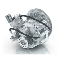
| Type | Marine Transmission |
|---|---|
| Series | 400 Series |
| Manufacturer | ZF |
| Application | Marine |
| Max Input Power | Varies by model (Consult ZF specifications) |
| Rated power (hp) | Varies by model (Consult ZF specifications) |
| Max Input Speed | Varies by model (Consult ZF specifications) |
| Gear Ratios | Varies by model (Consult ZF specifications) |
| Weight (kg) | Varies by model (Consult ZF specifications) |
| Weight (lbs) | Varies by model (Consult ZF specifications) |
| Mounting | Varies by model (Consult ZF specifications) |
| Housing Material | Aluminum |
| Oil Capacity (L) | Varies by model (Consult ZF specifications) |
| Oil Capacity (US qt) | Varies by model (Consult ZF specifications) |
| Cooling System | Integrated oil cooler (optional external cooler) |