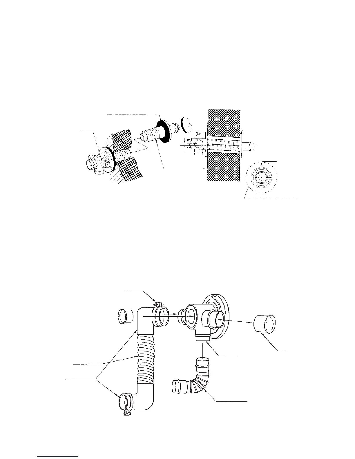
4. Attach the right-angled exhaust pipe bend to the
outlet of the exhaust pipe. Cut, if necessary, the flexible
air hose to size. Fasten the right-angled air hose to
both ends of the flexible air hose – now attach the
right-angled air hose to the inlet of the exhaust pipe.
Attach the right-angled air hose to both ends of the
flexible air hose. Now fasten the right-angled air hose
to the inlet of the exhaust pipe.
Fasten the right-angled air hose onto the inlet with a
hose clip. Seal the inlets and outlets that are not being
used with the caps supplied. Check that the caps are
firmly in position (See Fig.10). Use water or soap suds
to provide lubrication when fitting the right-angled air
hose onto the flexible air hose. The total length of the
exhaust pipe may be a maximum of 3 m (max. 3 bends).
Hose clip
Cap
Outlet
Right-angled exhaust bend
Right-angled air hose
Flexible air hose
c. From outside, insert the outer flue pipe through the hole. Secure the outer flue pipe to the wall by turning
it clockwise. This locks the two halves together (See Fig. 9).
I
MPORTANT: Make sure the arrow on the outer flue pipe frange is pointing up.
Make sure to secure the outer flue pipe well. (A-part shown in Fig. 9)



 To Next Page