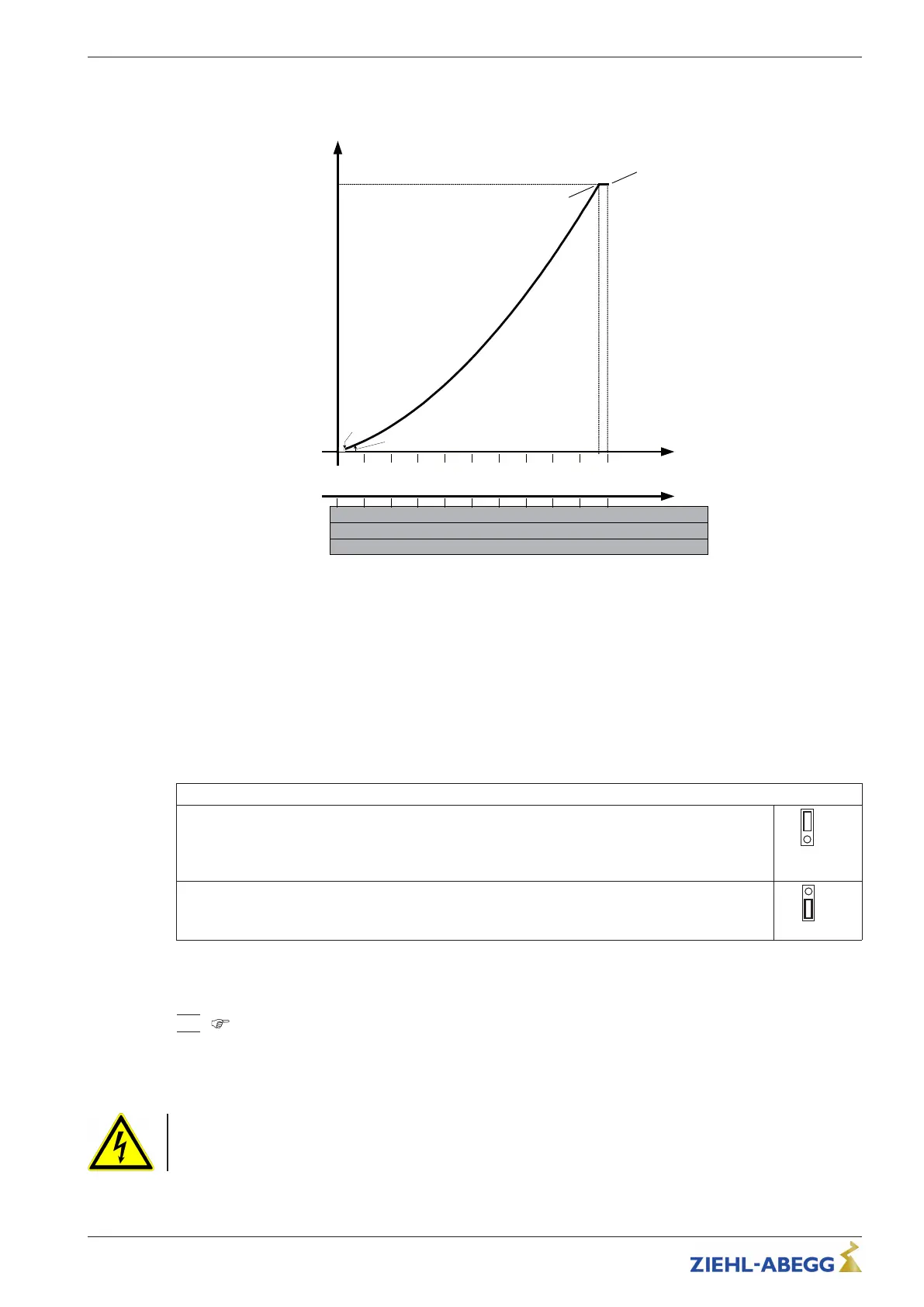
5.6.3 U/f-characteristic curve
Diagram setting signal and U/f curve (quadratic)
F
out
[Hz]
F
max
= 50 Hz
01.02.2013
v_u_f_fcon_basic_setsig.vsd
1 2
3
4 5
6 7 8
9
10
Analog In 1
0
45
50
403530
25
2015
10
5
2 4
6
8 10
12 14 16
18
20
0...10 V
0...20 mA
10 20
30
40 50
60 70 80
90
100
0...100 % PWM
F
edge
= 48.5 Hz
U
out
100 %
0.5
1
5
U
start
= 0 %
F
off
F
on
Analog In: Speed setting signal (0 - 10 V, 0...20 mA, 0...100 % PWM)
Fout: Output frequency
Uout: Output voltage
Ustart: Startvoltage
Foff: Shutdown Freq.
Fon: Switch on Freq.
Fedge: Edgefrequency
Fmax: Maximum frequency
5.7 Motor protection
Motor protection is possible by connecting thermostats “TB” (thermal contacts) or thermistors “TP”
(PTC).
The jumper “J1” in the connection space must be plugged according to the used thermal protectors.
Motor with thermistors “TP”
For motor with thermistors “TP” the jumper “J1” must be plugged at the top.
A maximum of six individual thermistors (DIN 44081 or DIN 44082) may be connected in series to
a single device.
Motor with thermostats “ TB”
For motor with thermostats “TB” jumper plugged at bottom (factory setting).
When a connected thermostat or thermistor responds (interruption between the two terminals
“TB/TP”) the device switches off and does not switch back on.
Relais “K1” is de-energized, terminals “13” - “14” interrupted. The internal signal lamp flashes in code
|
15
|
(
Diagnostics / faults).
Possibilities for re-starting after the drive has cooled down (terminals “TB/TP” bridged) by:
•
By switching the mains voltage off and then on again.
•
Via a digital input for remote control (ON/OFF enable).
Danger due to electric current
An outside voltage may never be connected to the terminals “TB/TP” and/or!
Operating Instructions Fcontrol Basic – model series FSDM2.5..50M Electrical installation
L-BAL-E162-GB 2022/02 Index 008 Part.-No.
16/30