09
Installation instructions & user manual
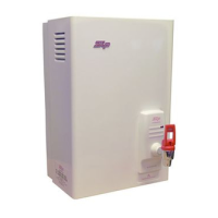
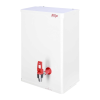
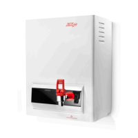
804545UK V2.03 Aug 2018 - Zip Hydroboil
Technical support
Tel: 0345 6 005 005 Email: service@zipindustries.co.uk www.zipwater.co.uk
Installation instructions
Electrical connection
Cable rating
• Connect products rated under 3kW via a 3 core cable, minimum cross sectional area of 1.5mm
2
.
• Connect 5.6kW rated products on dedicated ring main, via a 3 core cable, minimum cross sectional
area of 4.0mm
2
.
• Refer to current IEE guidelines for cable size and selection to ensure suitability for local installation conditions.
Exposed electrical connection
• Connect the cable to the terminal block, via the strain relief bush. (See diagrams above and pages 6 to 7).
• Tighten the strain relief bush, to secure the cable.
Concealed electrical connection
• Connect the concealed power cable through the rear access opening to the terminal block, via the strain relief
bush. (See diagrams above and pages 6 to 7).
• Tighten the strain relief bush, to secure the cable.
• Do not turn the power ON until the Hydroboil can dispense water from the tap outlet.
• Verify the earth continuity (see page 11).