STEP 4.
Connect the heart rate cables (14) protruding
out of the handlebar to the cables protruding
from the rear main frame (9). Then screw the
handrails (15 L/R) to the frame (9) using bolts
(12), flat washers (21), and nuts (6).
STEP 5.
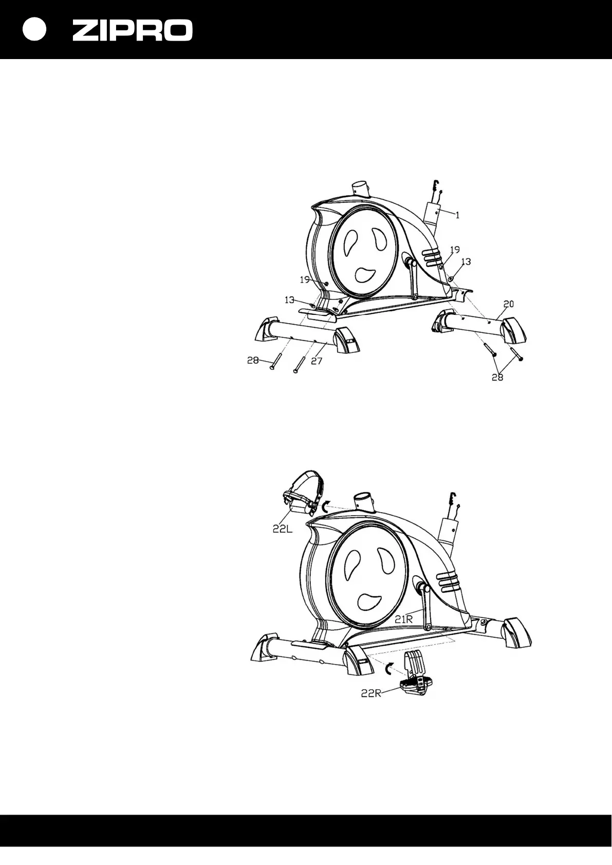
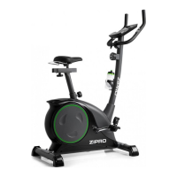
Screw the left and right pedal (27 L/R) to the
crank (46 L/R). Screw the right pedal bolt (27 R)
on clockwise. Screw the left pedal bolt (27 L)
counterclockwise.
NOTE! The right pedal is marked ‘R’, and the
left pedal is marked ‘L’.
STEP 6.
Connect the connecting cable (26) from the
main frame (1) to the upper connecting cable
(30) in the handlebar column (32) and the
sensor cable (28) to the upper sensor cable
(31).
Pull out the resistance adjustment cable (29)
through the opening in the handlebar bracket
(32) and connect it to the cable in the
resistance adjustment knob (33) as shown.
Insert the nut of the cable protruding from the
resistance adjustment knob (33) into the slot in
the bracket of the resistance adjustment cable
(29). Pull and tension the cable (33) and move it
through the cable (29) bracket vertically up.
Cable nut should be on the bracket as shown in
the picture.
Then screw the resistance adjustment knob
(33) on to the handlebar bracket (32) with the
cross-head bolt (35) and a flat washer (34).
Fix the handlebar bracket (32) to the front main
frame (1) with hexagonal bolts (20) and curved
washers (13).