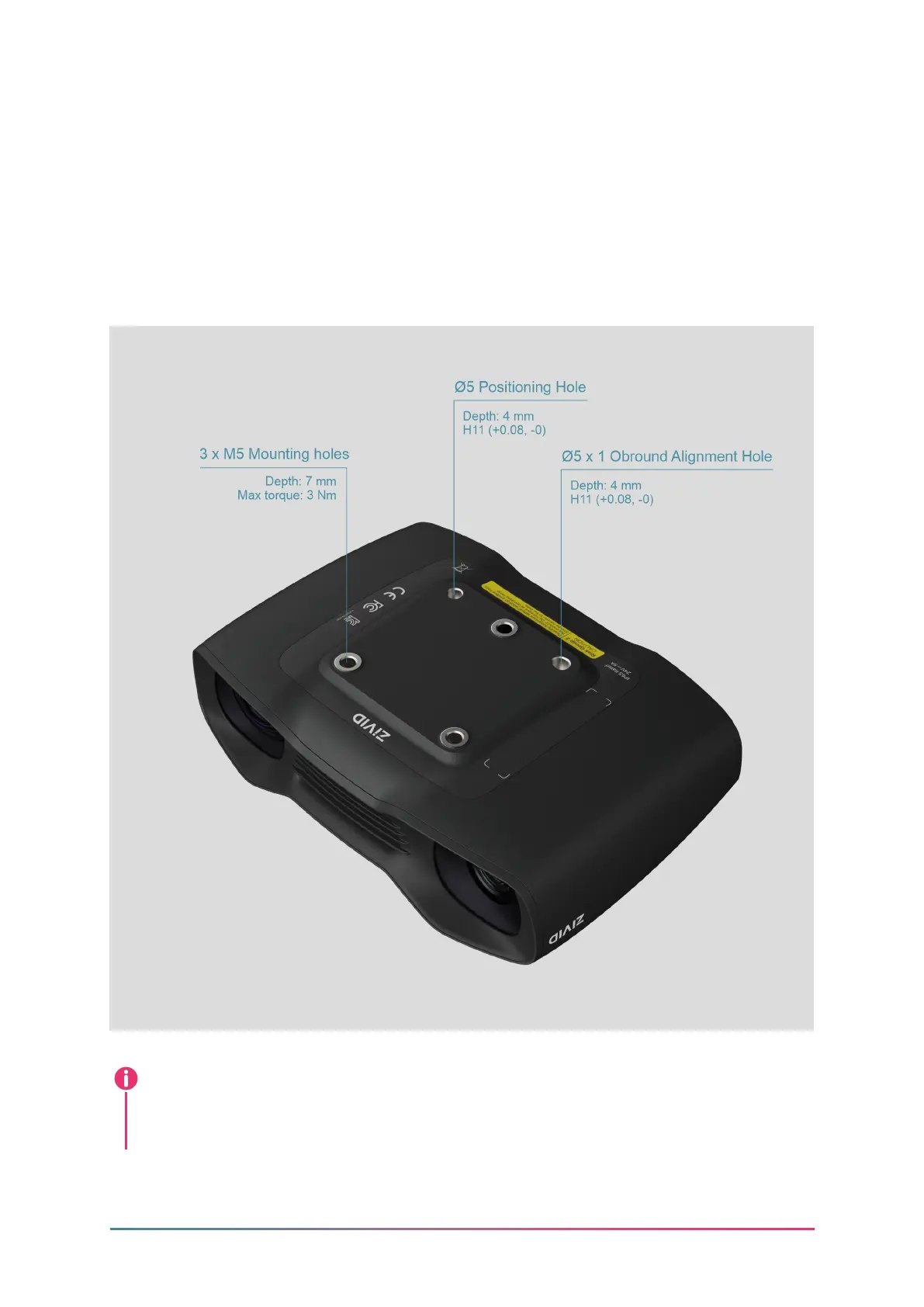
4.2 Mechanical Interface
The Zivid Two camera has three M5 mounting holes, one Ø5 positioning hole, and one
Ø5x1 obround alignment hole. We recommend using DIN 912 / ISO 4762 Hexagon or
ISO 14579 Hexalobular socket head cap screws in stainless steel (A2 or A4). To ensure
not to damage the threads, we recommend not exceeding the specied maximum
torque value when fastening the screws.
The camera must be completely still during the acquisition to deliver the spec-
ied 3D image quality. Otherwise, it is completely safe to move it, e.g. when
mounted on a robot or any other moving platform.
Note
Rev 1.0 - 9/2021 8 Zivid.com