6
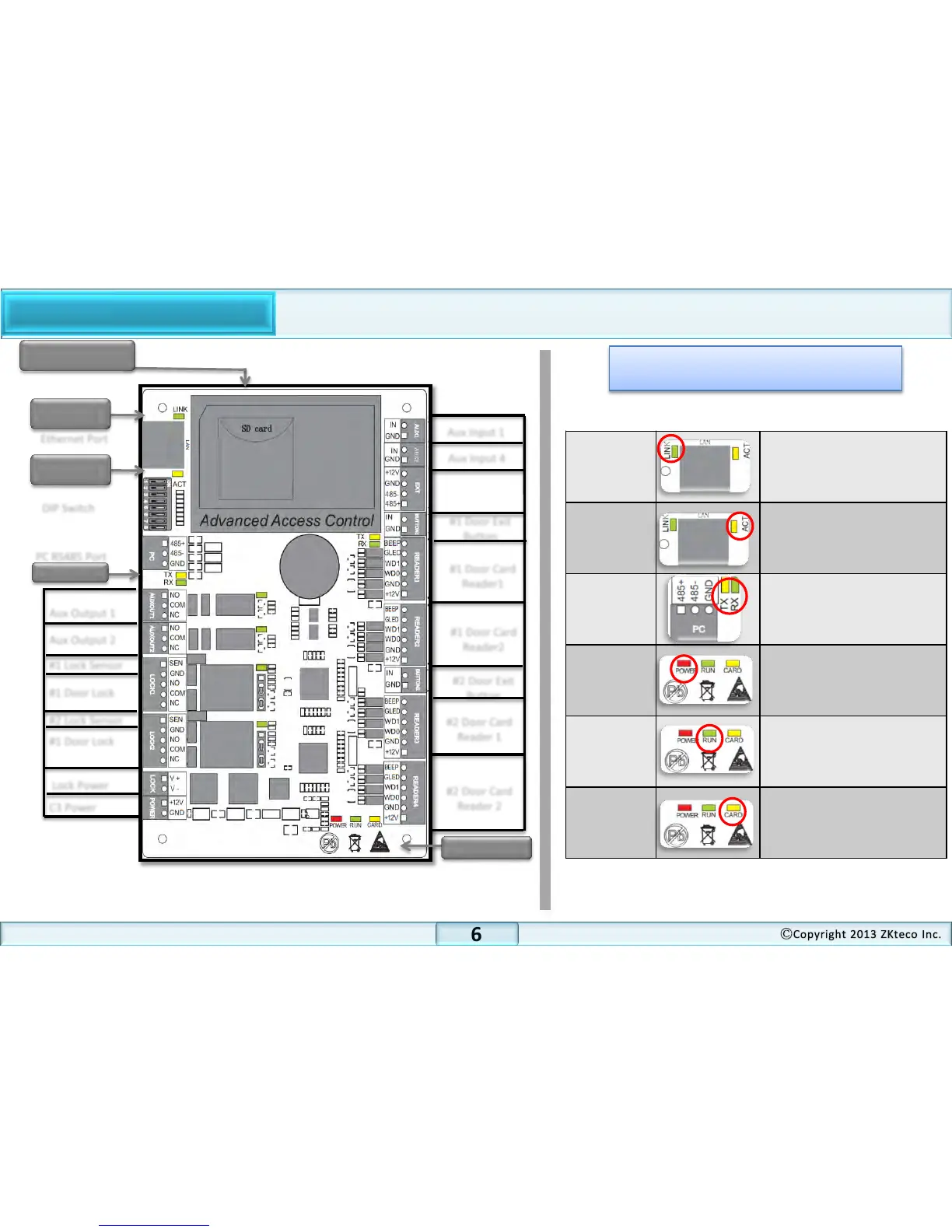
Product PIN Diagram
#2 Door Card
Reader 2
#2 Door Card
Reader 1
#1 Door Card
Reader1
#1 Door Exit
Button
Aux Input 4
Aux Input 1
SD Card Slot
LINK LED
ACT LED
Ethernet Port
DIP Switch
PC RS485 Port
Aux Output 1
Aux Output 2
Lock Power
C3 Power
LED indicators
LINK
(Green)
LED solid green indicates
TCP/IP communication is
normal
ACT
(Yellow)
Flashing LED indicates data
communication is in
progress
PC RS485
(Yellow &
Green)
Flashing LED is sending or
data in communication
progress
POWER
(Red)
Flashing LED indicates the
panel is powered on.
RUN
(Green)
Flashing LED indicates that
panel is in normal working
state
CARD
(Yellow)
Flashing LED indicates that