15
16
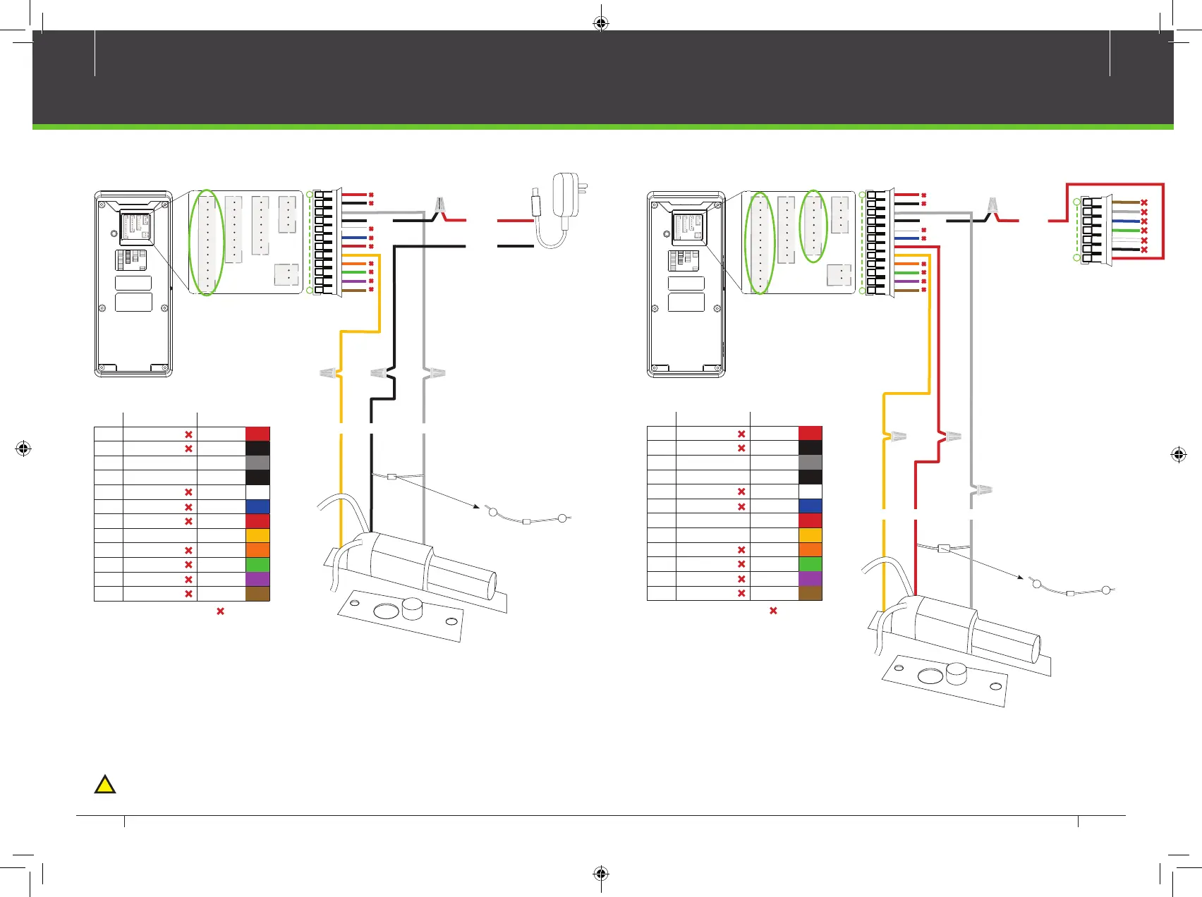
Lock Relay Connection
GND NC1Sensor
12V DCCOM1
Device does not Share Power With The Lock
Normally Closed Lock
12V DC Adaptor
GND
PIN DESCRIPTION WIRE
1 AL+
2 AL-
3 NC1
White
4 COM1
5 NO1
6 BUT Blue
7 GND
8 SEN Yellow
9 BELL+ Orange
10 BELL- Green
11
12
GND
Purble
Aux
Brown
Red
Black
Gray
Black
Red
Do not use
Notes:
1. The system supports NO LO CK and N C LOC K. For example the NO LO CK (normally open
at power on) is connected with 'NO1' and 'COM1' terminals, and the NC LOCK (normally close
at power on) is connected with 'NC1'and 'CO M1' terminals.
2. When electrical lock is connected to the Access Control System, you must parallel one FR107
diode (equipped in the package) to prevent the self-inductance EMF aecting the system.
!
Do not reverse the polarities.
RLED
RJ45-1
COM1
+12V
BUT
BELL+
BELL-
RJ45-3
GLED
AL-
IWD0
NO1
GND
RJ45-2
IWD1
NC1
GND
SEN
RJ45-6
BEEP
AL+
Ethernet
Alarm
Wiegand In
Output
Wiegand Output
RS485
Lock
Bell
Power Out
Sensor
Button
RXD
GND
WD1
TXD
485A
GND
485B
WD0
+12V
GND
GND
AUX
Auxiliary In
RS232
Power In
}
}
}
}
}
}
}
}
}
}
}
}
}
}
1
12
FR107
Diode
+
-
COM1
Device Shares Power With The Lock
FR107
Diode
+
-
GND
NC1
Sensor
Normally Closed Lock
12V DC
RLED
RJ45-1
COM1
+12V
BUT
BELL+
BELL-
RJ45-3
GLED
AL-
IWD0
NO1
GND
RJ45-2
IWD1
NC1
GND
SEN
RJ45-6
BEEP
AL+
Ethernet
Alarm
Wiegand In
Output
Wiegand Output
RS485
Lock
Bell
Power Out
Sensor
Button
RXD
GND
WD1
TXD
485A
GND
485B
WD0
+12V
GND
GND
AUX
Auxiliary In
RS232
Power In
}
}
}
}
}
}
}
}
}
}
}
}
}
}
PIN DESCRIPTION WIRE
1 AL+
2 AL-
3 NC1
White
4 COM1
5 NO1
6 BUT Blue
7 GND
8 SEN Yellow
9 BELL+ Orange
10 BELL- Green
11
12
GND
Purble
Aux
Brown
Red
Black
Gray
Black
Red
Do not use
1
12
1
7
2.4 Inch TFT Time Attendance &Access Control Terminal INSTALLATION GUIDE 2.4 Inch TFT Time Attendance & Access Control Terminal INSTALLATION GUIDE
 Loading...