ZLAC8015 Servo Driver Manual (Special for Hub Servo Motor) V2.00 ZLAC8015 Servo Driver Manual (Special for Hub Servo Motor) V2.00
13
Shenzhen ZhongLing Technology Co.,Ltd. TEL: +86-0755-29799302 FAX:+86-0755-2912 4283 WEB: www.zlingkj.com
Shenzhen ZhongLing Technology Co.,Ltd. TEL: +86-0755-29799302 FAX:+86-0755-2912 4283 WEB: www.zlingkj.com
14
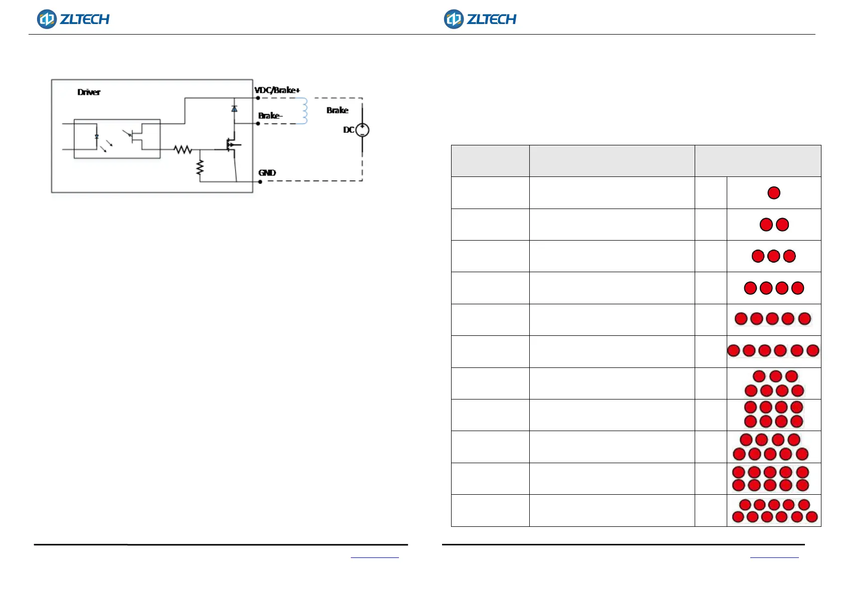
There are 2brake circuits, the schematic diagram is shown in Figure 5.
Fig.5 Output interface circuit
3.3. CANOPEN COMMUNICATION PORT DESCRIPTION
ZLAC8015D series driver provides 4PIN communication port. For pin definition,
please refer to 3.1.6 Communication Port, which includes CANH, CANL, CANH and CANL.
Note: Please use shielded twisted-pair cables for communication cable and make
ground connection to ensure stable communication.
3.4. RS485 COMMUNICATION PORT DESCRIPTION
ZLAC8015D series driver provides 8PIN communication port. For pin definition,
please refer to 3.1.6 Communication Port.
Note: Please use shielded twisted-pair cables for communication cable and
make ground connection to ensure stable communication.
3.5. STATUS INDICATOR LED
The green LED is power indicator, which is always on when the driver is powered on;. It
is off when the driver is powered off. The red LED is fault indicator. When the driver fails,
the driver will stop and prompt the corresponding fault code. The fault can be cleared
when the user powers off and restarts the power. The status indicator LED represents
different operation and fault information, as shown in the following table:
Status Situation
Status indicator LED
description
Over-Voltage
The power supply voltage exceeds the
maximum rated voltage.
1 Red
Under-Voltage
The power supply voltage is lower than
the minimum working voltage.
2 Red
Over-Current
Phase current through the motor
exceeds short-circuit between phases
3 Red
Over-Load
The phase current through the motor
exceeds the set overload current
4 Red
Current
out-of-tolerance
Control current and output current are
out of tolerance
5 Red
Position
out-of-tolerance
The given position is out of tolerance
with the output position
6 Red
Speed
out-of-tolerance
The given speed and output speed are
out of tolerance
7 Red
Internal reference
error
Internal fault of the driver 8 Red
Parameter reading
error
EEPROM parameters read error 9 Red
HALL fault
The HALL cable is not plugged in or the
signal is incorrect
10 Red
High motor
temperature
Motor temperature is too high 11 Red