H0412500.A - EN - 2013-02
6
EN
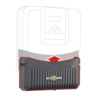
• Idenfy a suitable length (minimum 30 cm, without elbow) of straight
pipe.
• Dismantle the POD and keep the lower part with 2 holes,
• Turn the lower part of the collar upside down and place it in the posion
where you want to install it on the pipe.
• Use a center-punch or marker pen to mark the posion of the holes to be
made in the pipe.
• Using the holes saw supplied, cut the 2 feed holes for the POD.
Ensure that the edges of the holes are smooth and deburred!
• Place the upper part of the POD on the pipe, sliding it into the previously-drilled holes.
The arrows on the upper part of the POD collar show the direcon of water ow.
Reducer (marked
'EU') Ø50 mm
Collar Ø63
• Click the 2 parts of the POD collar together around the pipe. For a Ø50 mm pipe, use the reducer
labeled 'EU'. Do not use this reducer for a Ø63 mm pipe.
• Posion the upper part of the POD with its various components in the direcon indicated by the
foolproof locang notch and ghten the locking ring rmly (hand-ghten only).
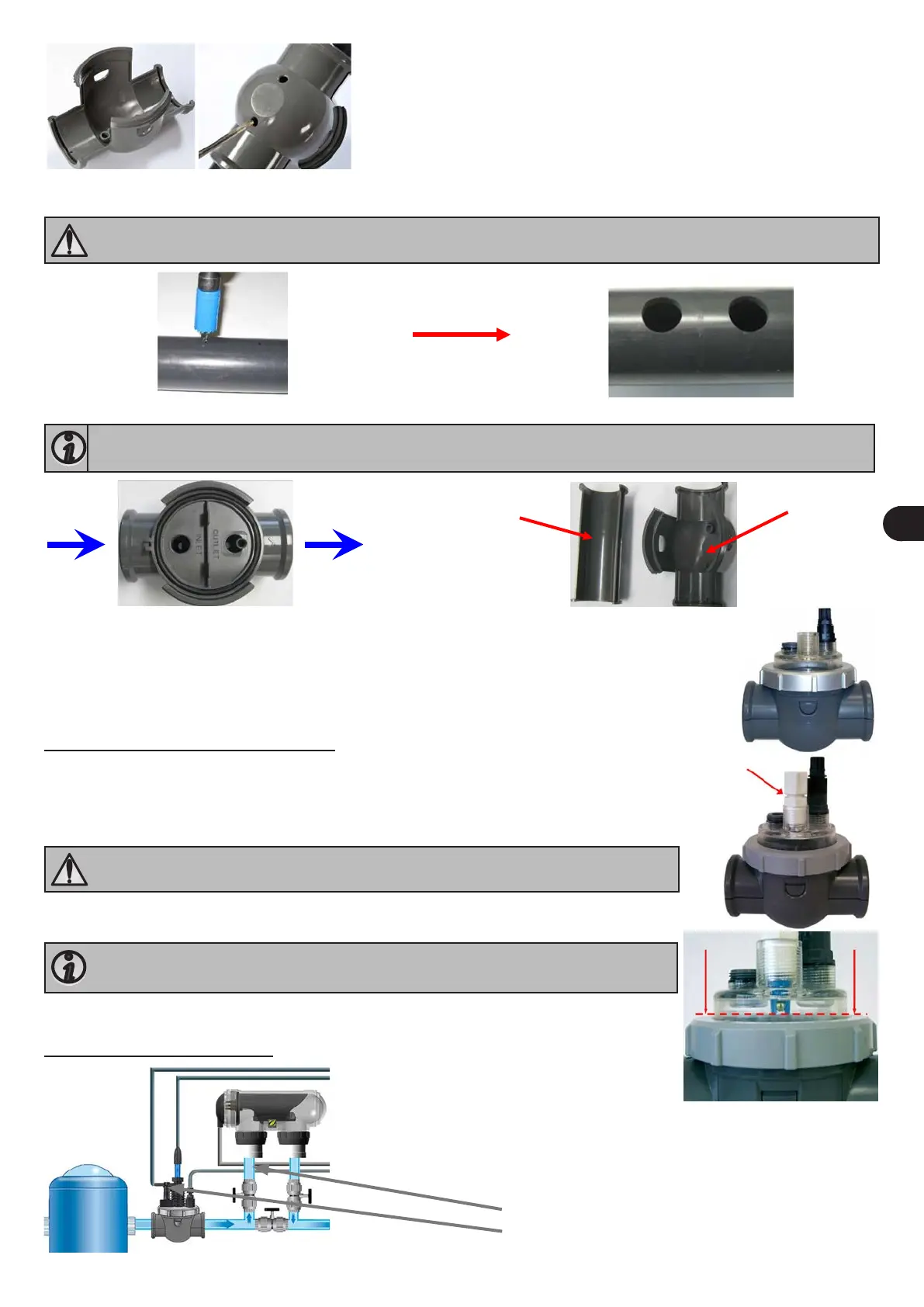
2.3.1 Installing the pH and ACL sensors
• Take the sensor holder(s) and put 10 to 12 turns of PTFE tape around its main thread.
• Screw the sensor holder into its seat on the POD.
• Carefully unscrew the protecve bole from the sensor.
• Rinse the end of the sensor with tap water and shake o excess water.
Never wipe the sensor using a cloth or paper ssue, as this may damage it!
• Insert the sensor into the sensor holder and hand-ghten the locking ring.
Ensure that the sensor is not inserted too far (see photo with a doed line marking
the inseron limit).
• Once installed, the sensors can be connected to the TRi power pack using the BNC sockets
labeled 'pH' (blue) and 'ACL' (red). They must now be calibrated (see § 3.3).
2.3.2 Installing the ow switch
Possible posions of the ow switch:
- aer the upstream valve if the cell is bypassed
- on the POD if the cell is in-line