Do you have a question about the Zoeller 7008 and is the answer not in the manual?
This document describes the Zoeller Models 7008, 7009, and 7010 Submersible Grinder Units, which are designed for grinding and pumping sewage in residential and commercial applications. These units are built with high-quality workmanship and an easy-maintenance design, intended to provide years of trouble-free service when installed according to manufacturer recommendations.
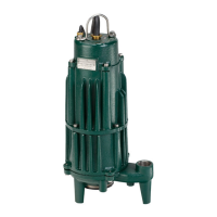
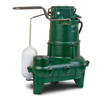
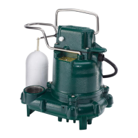
The Zoeller submersible grinder units are engineered to effectively grind and pump sewage, including reasonable quantities of items typically found in domestic sewage. They are suitable for both new installations and as direct replacements for other grinder applications of similar size and capacity. The pumps feature a robust construction with a cast iron powder-coated epoxy finish for long-life performance in submersible applications. The cutter assembly is comprised of 440C stainless steel components, hardened to a value of 55-60 on the Rockwell C scale, a two-bladed cutter, and a precision ground flat disk. This design allows for efficient grinding action, with the rotation of the cutter in a clockwise direction (viewed from the inlet). The motor is housed in a sealed compartment, and the pump is designed for intermittent duty sanitary sewage applications.
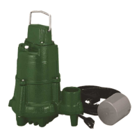
The grinder units can be installed in either indoor or outdoor prepackaged systems, as well as field-assembled systems. For automatic models, a float switch is included and factory-wired into the pump circuit to provide automatic operation. The float switch needs to be properly secured to the outlet pipe, and its tether length can be customized to achieve the desired on-off cycle for each application. The minimum "off" level is specified to ensure proper operation.
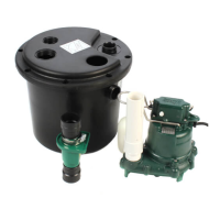
For prepackaged indoor systems, the units are preassembled at the factory, requiring minimal field assembly. All work inside the basin can be performed via an inspection port, and the pump and float switches are already set within the basin. The inlet hub location is determined by the inlet pipe arrangement and should be between the top lip of the basin and the alarm float "on" level, with a minimum distance of 10 inches between the basin floor and the hub. The inlet hub is designed for 4" pipe and should be installed on the side of the basin opposite the float switches.
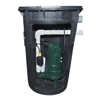
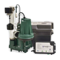
For prepackaged outdoor systems, similar preassembly is done at the factory. Float switches are set and tethered for proper operation. The alarm switch is typically located 3" above the pump "on" level. For systems with a control panel, multiple float switches are placed at specific distances from the bottom of the basin. The excavation for outdoor systems requires careful planning to avoid underground utilities and existing structure foundations, with the basin located at least ten feet from adjacent structures. A concrete anchor can be poured around the system to minimize movement, and the basin should be filled with water during this process.
Electrical connections for all models must comply with national, state, and local electrical codes. Automatic pumps are supplied with a 3-prong grounded plug for protection against electric shock, and the ground pin must never be removed. A disconnect switch should be installed ahead of the pump. Control panels, if used, should be equipped with proper size fuses and circuit breakers, and an independent power circuit is recommended. Junction boxes must have watertight connections, and a UL Listed potting kit is provided for sealing conduit connections to prevent warranty voidance.
During start-up, it is crucial to verify that pump power cables and control floats are properly installed, and voltage is correct. Conduit connections to the panel and junction box must be sealed. After installing the pump into the containment area with adequate submergence, the discharge valve should be fully open. If flow is less than rated performance, the pump may be air-locked and can be "jogged" several times using manual controls to expel trapped air. A qualified electrician should take voltage and current measurements with the pump running and record these readings.
Zoeller pumps are lubricated and tested at the factory, requiring minimal pre-start-up maintenance. The maximum operating temperature for the pump liquid is 130°F (54°C). Using the pump to dewater areas or pump liquids with heavy or abrasive materials will void the warranty.
For short-term storage, the pump should be stored indoors or covered with protective covering. The terminal ends of wire leads should be taped or sealed in a plastic bag, and unpainted surfaces should be spray-coated with rust-inhibiting oil. The impeller should be rotated every six months to prevent the seals from developing a permanent set. If a control panel is stored, it should be kept indoors in its shipping box, with all openings sealed, in an upright position, and nothing stacked on top.
Preventive maintenance is recommended to ensure a long service life. Every six months, the float operation should be checked for proper and unobstructed movement, and the check valve operation should be listened for. Every five years or 10,000 hours of operation, it is recommended to remove the pump, inspect and service it using a Zoeller rebuild kit, and flush and clean the basin.
Cutter maintenance is a key aspect of pump upkeep. All power circuits must be disconnected and locked out before any servicing. The cutter and disc can be removed and sharpened by grinding their cutting faces. This can be done in the field by removing the pump from the sump and positioning it horizontally to access the intake. If seals or other repairs are needed, the pump must be totally removed and serviced by a qualified pump technician or authorized service center.
To maintain optimal performance, the clearance between the cutter and disc should be checked with a feeler gauge, with the correct running clearance being between 0.004" and 0.008". To remove the cutter, the hex head bolt in the center of the cutter needs to be heated to 350°F to soften the thread lock sealant. A wood block can be used to prevent the cutter from turning while removing the bolt. After removing the cutter, the spacer shims located behind it should also be removed. The disc is held by six cap screws and can then be removed.
The disc and cutter can be replaced with new service parts or resurfaced by surface grinding to a 32 micro finish. This resurfacing should not be attempted in the field; parts should be sent to a qualified machine shop or returned to the factory for repair. The disc, cutter, and shims are a matched set and should be kept together. After resurfacing, the disc and cutter must be flat within 0.001". If the disc has been surface ground, shims of the same thickness as the material removed from the cutter disc must be removed to compensate. The final running clearance must be between 0.004" and 0.008".
When reassembling, the bottom of the pump where the disc is located should be cleaned, and the disc and retainer screws replaced, torqued to 63-67 in-lbs. The cutter should be replaced with the correct shims, and the hex head bolt torqued to 71-75 in-lbs, with Loctite 262 thread-lock sealant applied to the bolt threads. The running clearance should be checked again with the pump in a vertical position to remove end play.
Before reinstalling, the oil in the motor housing should be checked. If the oil has a milky appearance or burnt smell, the factory should be contacted. The oil level should be even with the fill plug when the pump is in an upright position, and insulating oil supplied by the factory should be used if additional oil is required.
In case of system shutdown for more than six months, if the pit is to remain dry, the pump can stay in the pit but should be operated for five minutes every three months. If the pit is to remain wet, the pump should be removed and stored as noted above. The control panel should have all openings sealed to prevent moisture and dust. Before restarting, the panel should be inspected for moisture and loose connections. Valve/actuator suppliers should be consulted for information on these components.
Troubleshooting common issues includes checking for blown fuses, low voltage, thermal overload, defective capacitors, clogged cutters or impellers, float switch issues, and incorrect wiring. For motor overheating, incorrect voltage, blocked impellers or cutters, negative head, and low oil level are common causes. If the pump does not shut off, air lock, debris under the float assembly, defective switch, or incoming sewage exceeding capacity may be the reason. Low or no water delivery can be due to clogged intake, air lock, low voltage, or a clogged discharge line. Frequent starts and stops can indicate a stuck check valve, undersized sump pit, or misadjusted level control. A large red flashing light on the control box typically signifies high water in the pit, clogging, or an overload trip. Accumulation of grease and solids in the pit can be addressed by breaking up solids and running the pump with water until the level lowers to the pump intake and solids are cleared. Kitchen grease should not be drained down the sink to prevent such accumulation.
| Model | 7008 |
|---|---|
| Horsepower | 1/2 HP |
| Voltage | 115V |
| Phase | 1 |
| Construction | Cast Iron |
| Type | Submersible |
| Maximum Head | 25 ft |
| Maximum Flow Rate | 42 GPM |
| Discharge Size | 1-1/2" NPT |
| Cord Length | 10 feet |
| Switch Type | Vertical Float Switch |
| Power Cord Length | 10 ft |