EasyManua.ls Logo

Zoeller 7013 - User Manual

Zoeller 7013
12 pages
Print Icon
To Next Page IconTo Next Page
Loading...
1
© Copyright 2015 Zoeller
®
Co. All rights reserved.
ZM2609_Ec
0715
Supersedes
0611
NOTICE TO INSTALLER: Instructions must remain with installation.
Model Number: ______________ Date Code: _______________
Simplex Duplex
Packaged System Field Assembled System
Job Name: ____________________________________________
Distributor: ____________________________________________
Date of Purchase: _________ Zoeller S/O No.: ______________
Contractor: ____________________________________________
Date of Installation: ____________________________________
System Readings During Start-up: Voltage _____ Amps ______
OWNER’S MANUAL
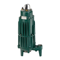
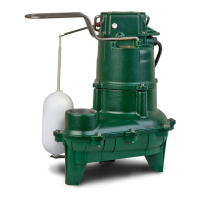
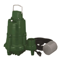
MODELS 7011, 7012 & 7013 SUBMERSIBLE GRINDER UNITS
aid in the ownership of a Zoeller submersible wastewater
product. Please read and review this manual before
installing the product. Follow the steps in this manual
for a proper start-up. Many items contained within,
when followed correctly, will not only ensure a long
and problem-free life for the pump, but also save
time and money during installation. Should further
assistance be necessary please call our Product
Support Department at +1 (502) 778-2731 or email:
zeptechnical@zoeller.com.
Owners Information
Safety Instructions
TO AVOID SERIOUS OR FATAL PERSONAL INJURY OR MAJOR
PROPERTY DAMAGE, READ AND FOLLOW ALL SAFETY
INSTRUCTIONS IN THIS MANUAL AND ON THE PUMP.
THIS MANUAL IS INTENDED TO ASSIST IN THE INSTALLATION
AND OPERATION OF THIS UNIT AND MUST BE KEPT WITH
THE PUMP.
This is a SAFETY ALERT SYMBOL.
When you see this symbol on the pump or in the
manual, look for one of the following signal words
and be alert to the potential for personal injury or
property damage.
Warns of hazards that WILL cause serious personal
injury, death or major property damage.
Warns of hazards that CAN cause serious personal
injury, death or major property damage.
Warns of hazards that CAN cause personal injury
or property damage.
INDICATES SPECIAL INSTRUCTIONS WHICH ARE
VERY IMPORTANT AND MUST BE FOLLOWED.
THOROUGHLY REVIEW ALL INSTRUCTIONS AND WARNINGS
PRIOR TO PERFORMING ANY WORK ON THIS PUMP.
MAINTAIN ALL SAFETY DECALS.
PUMPS WITH THE “UL” MARK AND PUMPS WITH THE “US”
MARK ARE TESTED TO UL STANDARD UL778. CSA CERTIFIED
PUMPS ARE CERTIFIED TO CSA STANDARD C22.2 NO. 108.
CAUTION
Table of Contents
Safety Instructions ....................................................................... 1
Limited Warranty and Application ..............................................2
Preinstallation Checklist .............................................................. 3
General Information ..................................................................... 4
Pump Wiring Instructions ............................................................5
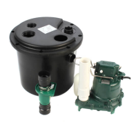
Typical Indoor Prepackaged System .......................................... 6
Indoor Prepackaged Installation Instructions ........................... 7
Typical Outdoor Prepackaged System ....................................... 8
Outdoor Prepackaged Installation Instructions ........................ 9
Operation ..................................................................................... 10
Cutter Maintenance .................................................................... 11
Service Checklist ........................................................................ 12
REFER TO WARRANTY ON PAGE 2.
Congratulations on the purchase of a Zoeller submersible
grinder pump. Since 1939, the name Zoeller has represented
the standard for submersible dewatering and sewage pumps.
The same high quality workmanship and easy maintenance
design has been incorporated into this line of heavy-duty
submersible grinder pumps. This Zoeller pump will provide
years of trouble-free service when installed according to the
manufacturer’s recommendations.
This manual incorporates the installation, operation,
maintenance, and service instructions into one document to
50/60Hz
Product information presented
here reects conditions at time
of publication. Consult factory
regarding discrepancies or
inconsistencies.
MAIL TO: P.O. BOX 16347 • Louisville, KY 40256-0347 USA
SHIP TO: 3649 Cane Run Road • Louisville, KY 40211-1961 USA
+1 (502) 778-2731 • FAX +1 (502) 774-3624
visit our web site:
zoellerengineered.com
Question and Answer IconNeed help?

Do you have a question about the Zoeller 7013 and is the answer not in the manual?

Summary

Safety Instructions

Preinstallation Checklist

Pump Wiring Instructions

Single Phase - 2 BHP Model 7011 Wiring

Covers lead identification and wiring diagram for single phase 2 BHP Model 7011.

Indoor Prepackaged System Installation Instructions

Typical Outdoor Grinder Pumping System Installation

Outdoor Prepackaged System Installation Instructions

Operation

Start-Up Procedure

Key checks and steps to perform before placing the pump into operation.

Cutter Maintenance

General Maintenance

Safety Procedures

Critical safety precautions to follow when performing maintenance or service.

Service Checklist

A checklist of common pump problems and their likely causes and solutions.

Overview

The document describes the Zoeller Models 7011, 7012, and 7013 Submersible Grinder Units, providing installation, operation, maintenance, and service instructions. These pumps are designed for grinding and pumping sanitary sewage from submersible lift stations, handling reasonable quantities of items normally found in sanitary sewage applications. They are suitable for new installations, direct replacements for similar grinder applications, and retrofitting existing positive displacement pump installations.

Function Description:

The Zoeller grinder pumps are heavy-duty submersible units designed for intermittent duty sanitary sewage applications. They effectively grind and pump sewage, preventing clogs in low-pressure pipe systems. The cutter assembly, made of stainless steel components hardened to 55-60 on the Rockwell C scale, consists of a star-shaped cutter and a precision ground flat disk. Cutting action occurs as the star cutter rotates at 3450 RPM against the stationary cutter plate. Model 7011 features a bidirectional cutter mechanism, allowing it to cut in either direction, with control panels offering a reversing feature to alternate rotational direction with each duty cycle. Models 7012 and 7013 have a single-directional cutter mechanism. The pumps are equipped with dual seals and seal leak probes. Single-phase units include an internal thermal overload, while three-phase pumps have a thermal sensor and require overload protection in the control panel.

Important Technical Specifications:

  • Construction: Class 30 cast iron, protected with powder-coated epoxy for long life.
  • Cutter Assembly: Stainless steel, hardened to 55-60 Rockwell C scale.
  • Motor Speed: 3450 RPM (for 60Hz models), 2800 RPM (for 50Hz models).
  • Maximum Operating Temperature: 130°F (54°C).
  • Electrical Data (60Hz models):
    • 7011 (1 Phase): 200V (20.0A Full Load), 230V (17.2A Full Load).
    • 7011 (3 Phase): 200V (12.3A Full Load), 230V (10.8A Full Load), 380V (6.8A Full Load), 460V (5.5A Full Load), 575V (4.5A Full Load).
    • 7012 (1 Phase): 200V (20.0A Full Load), 230V (17.2A Full Load).
    • 7012 (3 Phase): 200V (12.3A Full Load), 230V (10.8A Full Load), 380V (6.8A Full Load), 460V (5.5A Full Load), 575V (4.5A Full Load).
    • 7013 (1 Phase): 200V (20.0A Full Load), 230V (17.2A Full Load).
    • 7013 (2 Phase): 200V (12.3A Full Load), 230V (10.8A Full Load), 460V (5.5A Full Load), 575V (4.5A Full Load).
    • 7013 (3 Phase): 380V (6.8A Full Load).
  • Electrical Data (50Hz models):
    • AK7011 (3 Phase): 380V (4.4A Full Load).
    • AK7012 (3 Phase): 380V (4.4A Full Load).
    • AK7013 (3 Phase): 380V (4.4A Full Load).
  • Shut-off Head (60Hz): 7011 (104 ft / 31.7 m), 7012 (125 ft / 38.1 m), 7013 (125 ft / 38.1 m).
  • Recommended Application Limits (60Hz):
    • Simplex Station: 7011 (w/o reversing control) for 2 homes (3 m³/day), 7011 (w/ reversing control) for 2 homes (3 m³/day), 7012 for 2 homes (3 m³/day), 7013 for 2 homes (3 m³/day).
    • Duplex Station: 7011 (w/o reversing control) for 10 homes (15 m³/day), 7011 (w/ reversing control) for 15 homes (23 m³/day), 7012 for 10 homes (15 m³/day), 7013 for 10 homes (15 m³/day).
  • Basin Diameter: Recommended 24" (610 mm) for simplex systems, 36" (91 cm) or larger for duplex systems.

Usage Features:

  • Installation Flexibility: Can be installed as a prepackaged "Job Ready System" (indoor or outdoor) or as a field-assembled basin package.
  • Control Panels: Pumps are operated by control panels with variable level float control switches. Single-phase motors require a Zoeller-approved starting relay, starting capacitor, and run capacitor, all mounted in a control panel.
  • Air Lock Prevention: The pump case has an air vent located behind the discharge, which must be cleaned before each reinstall. An extra air vent hole (5 mm / 3/16") can be drilled in the discharge pipe below the check valve to further prevent air lock.
  • Electrical Safety: All electrical connections must comply with the National Electrical Code and local codes. A disconnect switch should be installed ahead of the pump. Junction box conduit must be watertight, and a UL Listed potting kit (P/N 10-2350) is available for sealing.
  • Float Switch Management: Float switches are factory-set and tethered for proper operation. Installers are responsible for verifying correct float switch placement to prevent hanging up and ensuring the pump shuts off. Cable ties used for shipping must be cut for proper operation.
  • System Start-up: After installation, the pump should be run using manual controls with adequate submergence. If flow is low, the pump may be air-locked and should be "jogged" several times using manual controls to expel trapped air. Voltage and current measurements should be taken by a qualified electrician during operation.

Maintenance Features:

  • Pre-start-up: Zoeller pumps are lubricated and tested at the factory, requiring minimum pre-start-up maintenance.
  • Short-term Storage: If not in use, the pump should be stored indoors or covered, wire leads taped/sealed, unpainted surfaces spray-coated with rust-inhibiting oil, and the impeller rotated every six months to keep seals lubricated. Control panels should be stored indoors in their shipping box, sealed, upright, and not stacked.
  • Shutdown Procedures: For systems shut down for more than six months, if the pit remains dry, the pump can stay in the pit but should be operated for five minutes every three months. If the pit remains wet, the pump should be removed and stored as noted above. Panels should be sealed to prevent moisture/dust and inspected for moisture/loose connections before restarting.
  • Preventive Maintenance (Every six months): Check for proper and unobstructed float operation, and listen for proper check valve operation.
  • Preventive Maintenance (Every 5 years or 10,000 hours): Remove pump, inspect, and service using a Zoeller rebuild kit. Flush and clean the basin.
  • Cutter Maintenance:
    • Disassembly: Disconnect power, remove the plastic guard ring, heat the hex head bolt (to 350°F / 176°C) to soften thread lock sealant, remove the bolt, pull the star cutter from the shaft, and remove spacer shims. Remove the three cap screws holding the disc and remove the disc.
    • Resurfacing: The disc and star cutter can be replaced or resurfaced by grinding to a 32 micro finish. Resurfacing should be done by a qualified machine shop or returned to the factory. After resurfacing, parts must be flat within 0.001" (.025 mm). Shims may need to be removed to compensate for material loss.
    • Reassembly: Clean the pump bottom, replace the disc and retainer screws (torque to 63-67 in-lbs / 7.1-7.6 N.m). Replace the star cutter with correct shims, install washer, and torque the hex head bolt (71-75 in.-lbs. / 8-8.5 N.m) with Loctite 262 thread-lock sealant.
    • Clearance: The correct running clearance between the star cutter and disc must be between 0.004" (0.1 mm) and 0.008" (0.2 mm).
    • Oil Check: Check the oil in the motor housing before reinstalling. Contact the factory if the oil is milky or burnt. The oil level should be even with the fill plug when the pump is upright. Use insulating oil supplied by the factory if refilling is needed.
  • Troubleshooting: A service checklist provides common causes and solutions for issues like the pump not starting, motor overheating, pump not shutting off, low water delivery, frequent starting/stopping, alarm light activation, and grease/solids accumulation.

Zoeller 7013 Specifications

General IconGeneral
BrandZoeller
Model7013
CategoryWater Pump
LanguageEnglish

Related product manuals